background image

KSwitch D3 UMP Unmanaged PoE Ethernet Switch - User Guide, Rev. 1.0 


www.kontron.com 


// 22 


4.1.4.


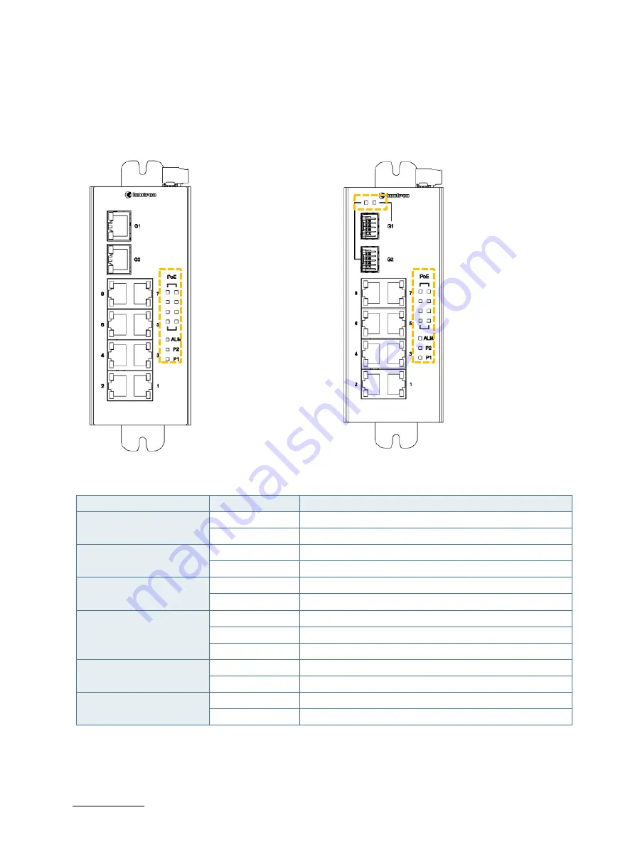
Indicator LEDs (P 1, P2, ALM, PoE, Link/Activity and Speed) 

The indicator LEDs show the normal operation of the switch and in the case of failure may be used for faultfinding. 
The Ethernet ports‘1’ to ‘8’ are PoE ports, each with a PoE LED, to indicate PoE operation. 

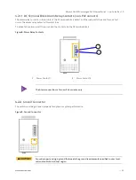
Figure 6: Indicator LEDs  


Table 4: Indicator LEDs 

LED Name 

Indicator /Color 

Condition 

PoE 

On Green 

PoE is working 

Off 

PoE is not working 

P1/P2 

On Green 

P1/P2 power line has power 

Off 

P1/P2 power line disconnect or does not have supply power  

ALM 

On Red 

Power failure alarm occurs 

Off 

No power failure alarm  

RJ45 Copper 
(Link/Act) 
 

On Green 

Ethernet link up but no traffic is detected 

Flashing Green 

Ethernet link up and there is traffic detected 

Off 

Ethernet link down 

RJ45 Copper 
(Speed) 

On Yellow 

1000Mbps connection detected 

Off 

No link or 10/100 Mbps connection is detected 

Fiber SFP Port (G1 & G2) 
(Link/Act) 

On Green 

SFP port speed 1000Mbps connection detected 

Off 

No Link 


Summary of Contents for kontron KSwitch D3 UMP

Page 1: ...USER GUIDE www kontron com KSwitch D3 UMP Unmanaged PoE Ethernet Switch Doc User Guide Rev 1 0 Doc ID 1068 1424...

Page 2: ...KSwitch D3 UMP Unmanaged PoE Ethernet Switch User Guide Rev 1 0 www kontron com 2 This page has been intentionally left blank...

Page 3: ...nty that such application will be suitable for the specified use without further testing or modification Kontron expressly informs the user that this user guide only contains a general description of...

Page 4: ...ations is entirely at your risk To minimize the risks associated with your products and applications you should provide adequate design and operating safeguards You are solely responsible for complian...

Page 5: ...isiting https www kontron com support and services kontron europe and asia support contact support Customer Service As a trusted technology innovator and global solutions provider Kontron extends its...

Page 6: ...ated and or prescribed by the law may endanger your life health and or result in damage to your material ESD Sensitive Device This symbol and title informs that the electronic boards and their compone...

Page 7: ...iggybacks Serious electrical shock hazards can exist during all installation repair and maintenance operations on this product Therefore always unplug the power cable and any other cables which provid...

Page 8: ...or conductive circuits on the product Lithium Battery Precautions If your product is equipped with a lithium battery take the following precautions when replacing the battery Caution Risk of Explosio...

Page 9: ...s used are capable of being recycled Final disposal of this product after its service life must be accomplished in accordance with applicable country state or local laws or regulations WEEE Compliance...

Page 10: ...15 3 1 Packaging 15 3 2 Unpacking 15 3 3 Scope of Delivery 15 3 4 Accessories 15 3 5 Product Identification Type Label Example 17 4 Features 18 4 1 Faceplate Features 19 4 1 1 RJ45 Copper PoE Ethernet...

Page 11: ...ronmental Specification 30 Table 7 Certification Compliance 30 Table 8 Mechanical Specification 30 Table 9 Electrical Specification 31 Table 10 List of Acronyms 35 List of Figures Figure 1 KSwitch Typ...

Page 12: ...ide To ensure you have the latest version of this user guide visit Kontron s KSwitch Industrial Ethernet Switches at https www kontron com products systems ethernet solutions This user guide provides...

Page 13: ...Source LPS and Power Source PS2 of UL IEC 62368 1 Only products or parts that meet the requirements for Power Source PS1 of UL IEC 62368 1 may be connected to the product s available interfaces I O Be...

Page 14: ...a beam emitted by a laser source damage to the eye from viewing a connector attached to a broken fiber or an energized fiber 2 2 Electrostatic Discharge ESD A sudden discharge of electrostatic electri...

Page 15: ...formation for handling the switch 5 Check the contents for visible shipping damage If you notice any shipping damage or inconsistencies between the contents and the original order contact Kontron for...

Page 16: ...emp 40 85 C EN SFP G ZX70 T 1 Gigabit SFP Modules 1000Base ZX single mode transceiver 80km 1550nm wide operating Temp 40 85 C EN SFP G TX00 T 1 Gigabit SFP Modules 1000Base TX transceiver RJ45 connect...

Page 17: ...ct Identification Type Label Example Figure 1 KSwitch Type Label 1 Model full name 2 Series name 3 Part Number PN with bar code 4 Revision 5 Serial Number SN with barcode 6 Production date 7 Electrica...

Page 18: ...eight 10 100 Mbps Ethernet ports that meets the IEEE 802 3af at standard with 15 4 W 30 W PoE output and up to two 10 100 1000 Mbps copper fiber ports Figure 2 KSwitch D3 UMP Unmanaged PoE Ethernet In...

Page 19: ...Twisted Pair or STP Shielded Twisted Pair Ethernet cables The switch supports eight 10 100 Mbps copper Ethernet ports labeled 1 to 8 and two ports G1 and G2 that are either copper 10 100 1000 Mbps Eth...

Page 20: ...re IEEE 802 3af at compliant PoE PoE ports When connected to a Powered Device PD the switch automatically detects if the PD is PoE or PoE and powers accordingly with either 15 4 W or 30 W full load Th...

Page 21: ...km or special application transceivers For each fiber port there is a transmit TX and receive RX signal When making fiber optic connections ensure that the transmit TX port of the switch connects to t...

Page 22: ...icator Color Condition PoE On Green PoE is working Off PoE is not working P1 P2 On Green P1 P2 power line has power Off P1 P2 power line disconnect or does not have supply power ALM On Red Power failu...

Page 23: ...clamp screws to prevent the wires from loosening Each of the DC power supplies should be capable of providing the required 250 W power budget The switch supports fault alarm notification for power Fi...

Page 24: ...rm relay output is Normal Close To activate the alarm insert the wires into the contacts on the DC terminal block Figure 8 Alarm Relay Contacts 1 Alarm Contact 1 2 Alarm Contact 2 The Alarm connection...

Page 25: ...l clip enabling the orientation of the DIN Rail clip to be changed by 180 Sets of mounting holes at the top and bottom sides of the rear side enable installation of wall mount plates For mounting info...

Page 26: ...ize M3 provided Figure 11 DIN Rail Clip 2 Hook the top of the DIN Rail clip over the DIN Rail and push the bottom of the switch towards the DIN Rail until the Din Rail clip snaps into place 5 2 DIN Ra...

Page 27: ...ooth and meets the thickness requirement of the screw 2 Aline each wall mount plate to the correct threaded holes top and bottom on the rear side of the switch Mount on a wall or flat surface using th...

Page 28: ...ed in your local national and international region If access to power is restricted guarantee disconnection using a separate cut off device 6 1 Connecting to DC Terminal Block To connect the switch to...

Page 29: ...bles Auto negotiation Duplex 10 100 1000 Mbps speed auto negotiation full half duplex Ethernet Port Protection 1 5 KV VRMS 1 minute Hipot 2 KV surge immunity on RJ45 copper ports PoE IEEE 802 3af at 1...

Page 30: ...ation Compliance Certification 10 port EMC EN 61000 6 3 Class B EN 61000 6 4 EN 61000 6 2 and EN 55035 Safety UL IEC EN 62368 1 FCC According to requirements of 47 CFR FCC Part 15 Subpart B Class A ru...

Page 31: ...ore connecting to power connect the ground cable to the ground connector and ensure that the installation sites ground meets the grounding requirements specified in your local national and internation...

Page 32: ...nce or repair on the switch may only be carried out by qualified personnel authorized by Kontron Return the switch to Kontron for maintenance and repair see Chapter 9 1 Returning Defective Merchandise...

Page 33: ...iod Follow these steps before returning any product to Kontron 1 Visit the RMA Information website http www kontron com support and services support rma information Download the RMA Request sheet for...

Page 34: ...y accident liability obligations in the event of damage caused to the product due to failure to observe the following General safety instructions for IT equipment within this user guide Warning labels...

Page 35: ...Limited Power Source MAC Media Access Control MDI Medium Dependent Interface MDIX Medium Dependent Interface cross over MIB Management Information Base MLD Multicast Listener Discovery MSTI Multiple S...

Page 36: ...ry 4 0 applications With its standard products and tailor made solutions based on highly reliable state of the art embedded technologies Kontron provides secure and innovative applications for a varie...

Reviews: