KSwitch D3 UMP Unmanaged PoE Ethernet Switch - User Guide, Rev. 1.0
// 23
4.2.
Top Side Features
4.2.1.
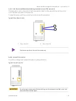
DC Terminal Block Power Contacts
The switch can be powered from dual external DC power supplies (input range: 24 VDC to 48 VDC) by inserting the
positive and negative wires into the corresponding contacts for the first power supply P1+/- and second power
supply P2+/- on the DC terminal block and tightening the wire-clamp screws to prevent the wires from loosening.
Each of the DC power supplies should be capable of providing the required 250 W power budget.
The switch supports fault alarm notification for power.
Figure 7: Power Contacts
1
P2+ contact
2
P2– contact
3
P1+ contact
4
P1- contact
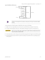
When connecting the power follow the polarity indicated for P1+/-and/or P2+/-.
Input power must be within the range of 48 VDC to 56 VDC for PoE compliant, or 42.5 VDC to
57 VDC for PoE+/PoE++ compliant.
With multiple power sources connected to the switch, the switch utilizes the power supply
with the higher voltage or the most stable power supply.
2
1
3
4


