KWS 3000-CML - User Guide, Rev.1.0
// 31
To close and secure the service cover, perform the following:
1.
Position the service cover above the main chassis approximately 20 mm away from the front panel.
2.
Lower the service cover to rest on the main chassis.
3.
Slide the service cover carefully towards the front panel until the metal catches on the front side of the service
cover connect with the front panel’s internal plate.
4.
Secure the service cover using the three screws retained in the previous step 2.
7.2.1.
Installing and Removing PCIe Cards
Before Installing a PCIe expansion card consider the motherboard’s connector slots interfaces and space
requirements (see Table 7: PCIe Expansion Cards).
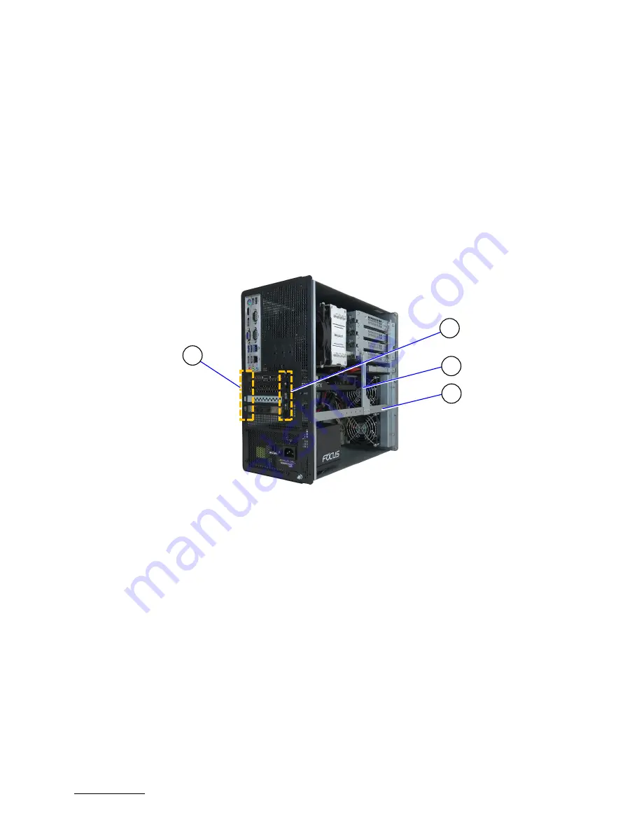
Figure 13: PCIe 3.0 Expansion Cards Slots
1
Slot bracket latches
(Top: slot 1 to Bottom: slot 4)
2
Slot bracket screws
(Top: slot 1 to Bottom: slot 4)
3
Short bracket
4
Long bracket
To install a PCIe expansion card,
perform the following
:
1.
Shut down the product properly using power button, PSU switch and disconnect the power cable from the
input power socket or mains power outlet
2.
Open the service cover, see Chapter 7.2: Opening and Closing the Service Cover.
3.
If the PCIe card’s size requires removal of the short bracket and/or long bracket, before removing the
bracket(s) note the original position of the short and/or long bracket(s) and screws.
4.
Remove the screws securing the short bracket to the drive cage and the long bracket. If removal of the long
bracket is required, remove the screws securing the long bracket to the sides of the chassis. Retain the screws
for later use.
5.
Remove the screw for the PCIe slot bracket that corresponds to the required motherboard PCIe connector (see
Table 7: PCIe Expansion Cards) and lift the PCIe slot bracket out of the latch. Retain the blank PCIe slot bracket
with screw for later use.
1
2
4
3


