background image

GEN6-3

Blueprint for the steam engine

4.5KW

264.5mm

372mm

6K /9KW 

372mm

264.5mm

333mm

372mm

162mm

333mm

372mm

200mm

Safety valve

Steam outlet

Water inlet

Water drain

162mm

333mm

Manual water 

drain

200mm

333mm

Water inlet

Safety valve

Steam outlet

Manual 

water drain

Water drain

!

provided is limited, do not operate on the pipeline and electric equipment arbitrarily as shown 
in the figure for proportion.


Caution


To avoid damage to the equipment, do not connect strong electric current 

directly to the components

!

To facilitate maintenance, keep the steam engine clean. If the information 

Attention


Summary of Contents for BAGNODESIGN BAGNOSPA BDD-SPA-GEN6-3-A

Page 1: ...BDD SPA GEN6 3 A BAGNOSPA STEAM GENERATOR 6KW 380V50HZ WITH DIGITAL CONTROL PANEL BLUETOOTH MUSIC BOX 2X SPEAKERS WIFI BOX AND 4 RGB LIGHTS www sanipexgroup com ...

Page 2: ... 5 Electric requirements 6 Installation of the top light 7 Choose your type of machine 8 Maintenance of the steam engine 8 Configuration of steam generator 9 Cleaning of the steam generator 10 Cleaning process 11 Trouble shooting 11 Common troubles trouble shooting methods 12 Ampere Meter 13 Technical parameter 14 Figure Heating element and Power line assemble illustration 15 19 ...

Page 3: ...ich link the controller and the steam generator should be 6 5m 2 The steam generator should not be installed in the steam room 3 Not installed outdoor or in any places that will influence the security of the machine by the environment 4 Do not install it in the frigid loft or any places the water will freeze 5 Do not install it near the burnable and caustic object or chemical coal gas or dope thin...

Page 4: ...g for some time Must take some measures for example using the heat insulation tube to prevent the damage of the hot tube and keep the outlet away from the people 12 The controller must be installed in the steam room please refer to the chapterinstruction of the controller s installation and operation of the manual The steam generator including the controller are comply with the CE and UL certifica...

Page 5: ...esistant to temperature as high as 120 C or higher 4 The horizontal part of the steam pipe should be installed inclining to the steam outlet or in the direction of steam engine Do not bend it in a hape to make sure that the cooled water will not stay in the curved pipe of the steam pipe 5 The shorter the steam pipe the better Try to decrease the number of elbows and avoid abrupt turns Attention Do...

Page 6: ...f effect Inside wall in the steam room Drainpipe 1 2 According to national or local rules the steam engine drainage valve should be equipped with drainpipe The steam engine drains the water by using weight Attention The drainpipe should not incline upwards so as to facilitate the drainage of water Safety valve 1 Safety valve is a piece of safe equipment in order to prevent too much steam pressure ...

Page 7: ...n 200mm 333mm Water inlet Safety valve Steam outlet Manual water drain Water drain provided is limited do not operate on the pipeline and electric equipment arbitrarily as shown in the figure for proportion Caution To avoid damage to the equipment do not connect strong electric current directly to the components To facilitate maintenance keep the steam engine clean If the information Attention ...

Page 8: ...on Installation of the top light Light is available in 12V 220V 230V outputs Before connect to the light please consult with manufacturer to know what voltage the light is so as to avoid generator damage or cause danger If the light output is 12V the power of the light should not be more than 35W othwise transformer will be burned and cause danger If light input is 220v 240V light power should not...

Page 9: ...lls C Celia Heights exceeding 8 FT D Ceramic tile E Glass 2 walls ADD 75 1 Wait for the completion of automatic water discharge after each time of using the steam engine to make sure the water in the tank is discharged completely before cutting off power supply 2 There should not be any leakage or damage among the steam engine steam nozzle components and pipes They should be checked and repaired a...

Page 10: ...ation bracket 3 Circuit board 4 Steam Outlet 5 Pressure relief valve 6 Water fill valve 7 Water drain valve 8 Subsidiary water tank 9 Main water tank 10 Heating Element 105O C Hi limit Transformer 11 12 Terminal block Fuse Earth wire connector 16 17 15 14 13 18 Relay Water level sensor Manual water drain 7 ...

Page 11: ...off when from element and water tank When timer window shows countdown time is 00 00 TEMP window shows opl from hot pls switch on the manual drain ball valve at this time to drain the water from water tank When system detect lack of water for 1 minute system will switch on the water inlet valve to get water supply to water tank so as to continue cleaning water scale inside tank for 1 minute and dr...

Page 12: ...E0 The temperature sensor open circuit Water level sensor failure checking the control cable connection between the control panel to steam generator is loose or not E02 The temperature sensor is Short circuit E03 Signal transfer fault between main panel and sub panel E04 Signal transfer fault between control panel and steam generator E12 E22 E32 E42 water inlet takes over 2 minutes E13 E23 E33 E43...

Page 13: ...hether the connection plug between the control panel and the electrically controlled box has become loose and whether the power circuitry has good contact 2 change a plugboard Water leakage 1 The water pipe connector becomes loose or the pipe breaks 2 Water leakage in the water input valve or the water drainage valve 1 Tighten the loose connector and change the broken pipe 2 Change the water input...

Page 14: ... overflow protection and electricity leakage protection Important The list above is for reference only In actual checking and repairing based on the national and local codes ask professional service personnel to operate Technical parameter Steam Volume ml min Steam Production Time S TYPE GEN6 3 Power Output Potency Error Duration Resistance Steam Pressure Applicable space of the room m3 Water Tank...

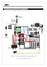
Page 15: ...5 20W Color Light 12V 10W G B VCC R Control Panel Music box WIFI box Sub Control Panel Horn2 Horn1 aroma pump Temp2 Temp1 25 c Real time Real time Internal wiring diagram of steam generator 4 5kw 220 240V 1phase Impor tant The parameter listed in the table will be varied from different place and temperature please consultate to the qualificatory designer and architect for the more detailed use ...

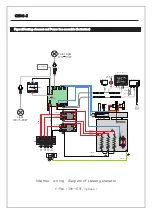
Page 16: ...Sub Control Panel Horn2 Horn1 Temp2 Temp1 25 c Real time Real time Internal wiring diagram of steam generator 6kw 220 240V 1phase 1 1 4 2 Black 2 0mm N L 3 2 2 0mm 2 0mm 2 0mm Yellow Red Red Black Red Yellow 2 0mm 2 0mm 2 0mm 2 0mm 2 0mm Light 12V 5 20W Color Light 12V 10W G B VCC R aroma pump 3 4 2 0mm 2 0mm ...

Page 17: ...emp2 Temp1 25 c Real time Real time Internal wiring diagram of steam generator 7 5 9kw 220 240V 1phase 1 1 6 2 Black 2 0mm N L 3 2 2 0mm 2 0mm 2 0mm Yellow Red Red Black Red Yellow 2 0mm 2 0mm 2 0mm 2 0mm 2 0mm Light 12V 5 20W Color Light 12V 10W G B VCC R aroma pump 3 4 2 0mm 2 0mm 5 6 4 5 2 0mm 2 0mm 2 0mm 2 0mm copper short circuit board ...

Page 18: ...ntrol Panel Music box WIFI box Sub Control Panel Horn2 Horn1 Temp2 Temp1 25 c Real time Real time Internal wiring diagram of steam generator 6 9kw 380 415V 3phase 1 2 Black 2 0mm N L1 L2 L3 2 0mm 2 0mm 2 0mm Yellow Red Red Black Red Yellow 2 0mm Light 12V 5 20W Color Light 12V 10W G B VCC R aroma pump 3 4 2 0mm 2 0mm ...

Page 19: ...Note ...
Page 20: ...IND SPA GEN6 3 A 12 21 www sanipexgroup com ...

Reviews: