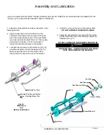
e. Install the scraper blades onto the dasher assembly
by holding the blades perpendicular to the tabs (Fig.
14) and then snapping them over the flat area of the
support rod. Then rotate the blades downward in a
counterclockwise direction as viewed from the front
of the dasher (Fig. 15).
BE CERTAIN THAT THE
SCRAPER BLADES REST UPON THE DASHER
TABS.
Note:
Reverse the blades at each cleaning to maintain
sharpness. In addition, the blades are equipped
with a wear mark (Fig. 16). When the blade is
worn to this wear mark, it must be replaced.
Blade Support
Tab
Support Rod
Dasher Front View
Scraper Blade
Dasher Front
View
Blade Support
Tab
Support Rod
Scraper Blade
Rotate Down
Counter
Clockwise
Scraper Blade Wear Mark
End
View
Side
View
ASSEMBLY and LUBRICATION
PAGE 7
Fig. 15
Scraper Blade Installation
Fig. 14
Scraper Blade Installation
Fig. 16
Scraper Blade Wear Mark
f. Insert the dasher assembly into the freezing cylinder
as far as possible (Fig. 17) being careful not to
damage the scraper blades. Damage will occur to
the scraper blades and the dispenser will not
operate properly if the scraper blades are installed
facing in a clockwise direction (Fig. 18).
Note: The stator rod has been deleted from Fig. 17 and
Fig. 18 for clarity only. The stator rod must be installed
for proper machine operation.
g. While maintaining force against the dasher, rotate it
slowly until the tongue of the dasher engages the
groove in the drive system at the rear of the cylinder.
The outer most portion of the dasher should be
recessed approximately 1/4” (6 mm) to 3/8” (10 mm)
inside the freezing cylinder. No part of the dasher
should extend outside the cylinder. Scraper blades
should be visible, extending approximately 1/8” (3
mm) beyond the dasher
(Fig.
19).
Fig. 17
Dasher Installation
CORRECT
Blades
Resting On Tabs
Blades Pointing In A
Counterclockwise
Direction
Fig. 18
Dasher Installation
Blades Should
Rest On Tabs
Blades Should Not Point
In A Clockwise Direction
INCORRECT
Summary of Contents for A7081HEP
Page 2: ......
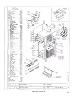
Page 17: ...PAGE 16 ASSEMBLY DIAGRAM ...
Page 18: ...Notes ...
Page 19: ...Service Log ...


