iII
Table of Contents
Illustrations
TABLE OF CONTENTS
Introduction ........................................................................................................................................................................ 1
Installation ......................................................................................................................................................................... 1
Disassembly and Cleaning ................................................................................................................................................ 2
Assembly and Lubrication ................................................................................................................................................. 5
Sanitizing ........................................................................................................................................................................... 8
Operation ........................................................................................................................................................................... 8
Helpful Hints ...................................................................................................................................................................... 9
Mechanical Consistency Control System ........................................................................................................................ 10
Routine Maintenance....................................................................................................................................................... 11
Troubleshooting ............................................................................................................................................................... 13
Exploded View................................................................................................................................................................. 15
Wiring Diagram ................................................................................................................................................................ 16
Service Record ................................................................................................................................................................ 18
Fig. 1 Leg
Installation ................................................................................................................................................... 1
Fig. 2 Control
Switch .................................................................................................................................................... 2
Fig. 3 Carburetor
Tube
................................................................................................................................................ 2
Fig. 4 Dispensing
Product ............................................................................................................................................ 2
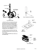
Fig. 5 Front Plate Assembly ......................................................................................................................................... 3
Fig. 6 O-Ring
Removal................................................................................................................................................. 3
Fig. 7 Carburetor
Tube ................................................................................................................................................. 3
Fig. 8 Dasher
Assembly ............................................................................................................................................... 3
Fig. 9 Scraper Blade Removal ..................................................................................................................................... 4
Fig. 11 Drip Tray Assembly ............................................................................................................................................ 4
Fig. 12 Stator Rod and Dasher Lubrication .................................................................................................................... 5
Fig. 13 Dasher Assembly ............................................................................................................................................... 5
Fig. 14 Scraper Blade Installation and Wear Mark......................................................................................................... 5
Fig. 15 Dasher Installation.............................................................................................................................................. 6
Fig. 16 Dasher Installation.............................................................................................................................................. 6
Fig. 17 Dasher (Front View) ........................................................................................................................................... 6
Fig. 18 Spigot Plunger Lubrication ................................................................................................................................. 6
Fig. 19 Front Plate Assembly ......................................................................................................................................... 7
Fig. 22 Carburetor Tube Assembly ................................................................................................................................ 7
Fig. 25 Drip Tray Assembly ............................................................................................................................................ 7
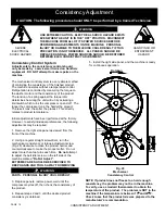
Fig. 28 Consistency Control ......................................................................................................................................... 10
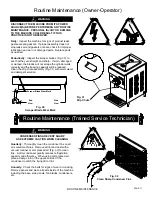
Fig. 30 Scraper Blade Wear Mark ................................................................................................................................ 11
Fig. 31 Drip Chute ........................................................................................................................................................ 11
Fig. 32 Clean Sharp Condenser Fins ........................................................................................................................... 11
Fig. 33 Torque Spring Adjustment Mechanism ............................................................................................................ 12


