background image

3

Grounding Instructions

This appliance must be grounded. If it should malfunction or
breakdown, grounding provides a path of least resistance for
electric current to reduce the risk of electric shock. This
appliance is equipped with a cord having an equipment-
grounding conductor and grounding plug. The plug must be
plugged into an appropriate outlet that is properly installed
and grounded in accordance with all local codes and
ordinances.

DANGER

Improper connection of an equipment-grounding conductor
can result in risk of electric shock. Check with a qualified
electrician or service person if you are in doubt as to whether
the outlet is properly grounded. Do not modify the plug provided
with the appliance. If it will not fit the outlet, have proper outlet
installed by a qualified technician.

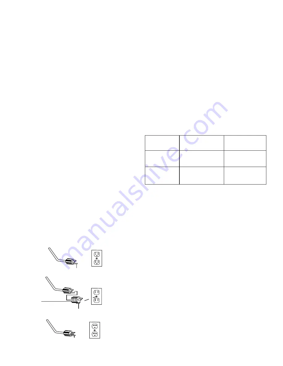
This appliance is for use on a nominal 120 volt circuit and has
a grounding plug that looks like the plug illustrated in Figure
1. A temporary adapter which looks like the adapter illustrated
in Figure 2 may be used to connect this plug to a two-pole
receptacle, as shown, if a properly grounded outlet is not
available. The temporary adapter should be used only until a
properly grounded outlet, Figure 1, can be installed by a
qualified electrician. The green colored rigid ear, lug, or the
like extending from the adapter must be connected to a
permanent ground such as a properly grounded outlet box
cover. Whenever the adapter is used, it must be held in place
by a metal screw.

For floor finishing machines rated 150-250 volts:

If the machine is provided with an attachment plug cap as
shown in Fig. 3, it is intended for use on a 240 volt (nominal)
circuit. No adapter is available for this application.

NOTE: In Canada, the use of a temporary adapter is not
permitted by the Canadian Electrical Code.

OPERATION/ACCESSORIES

Choosing the Right Brush and Drive Block

Your floor machine is packed complete and ready for use after
you install a brush or drive block. (Brushes and pads are not
provided with the unit but are available at an additional cost.)

Your floor machine is designed to be used for many different
floor care applications. Make sure you use the correct brush
or pad for the type of job you want to perform. (Accessories
are available from the dealer from whom the floor machine
was purchased.)

MACHINE SIZE

BRUSH DIAMETER

BLOCK DIAMETER

17”

17”

15”

20”

20”

18”

When ordering brushes or drive blocks, refer to this chart and
specify correct brush or block diameter when ordering.

FIGURE 1

FIGURE 2

FIGURE 3

G R O U N D E D
OUTLET BOX

Plug Grounding Pin

Grounding Tab

Metal Screw

Adapter

Plug Grounding Pin

Summary of Contents for 6000 Series

Page 1: ...k Cover For location of nearest Eureka Warranty Station or service information call 1 800 800 8975 En Mexico llame al 5670 6169 Please Retain We suggest you record the model type and serial numbers below They are located on the silver rating plate on your cleaner For prompt and complete service information always refer to these numbers when inquiring about service Model Type_______________________...

Page 2: ... not the cord Do not handle the plug or floor machine with wet hands Wind the cord no tighter than is necessary to retain it during storage Refer to Cord Storage Page 7 Use extra care when working near stairs Do not use in conjunction with flammable or combustible liquids such as gasoline or use in areas where explosive vapor or dust may be present Store your floor machine indoors in a cool dry ar...

Page 3: ...igure 1 can be installed by a qualified electrician The green colored rigid ear lug or the like extending from the adapter must be connected to a permanent ground such as a properly grounded outlet box cover Whenever the adapter is used it must be held in place by a metal screw For floor finishing machines rated 150 250 volts If the machine is provided with an attachment plug cap as shown in Fig 3...

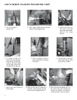
Page 4: ...e holes for the bolts Slide handle sleeve downward until all holes are lined up 5 Use a screwdriver to line up holes and guide bolts through the handle 6 Handle sleeve and bolts will look like this when they are properly installed 7 Attach lock nuts on bolts and fasten tightly 8 Remove wing nuts and washers to unfasten wood shipping retainer Discard wood shipping retainer 9 Secure the handle relea...

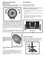
Page 5: ...river Fig 5 PAD CENTERING LOCK Model 20 1500 rpm 1 5 HP only To install a pad tip the machine backwards so it rests on the rear wheels and handle After centering the pad on the pad holder insert the Pad Centering Lock and twist it clockwise until it securely locks in place To remove twist the lock counterclockwise DRIVE BELT ADJUSTMENT Model 20 1500 rpm 1 5 HP only CAUTION Disconnect the power cor...

Page 6: ... rpm for scrubbing or 300 rpm for buffing Do not operate this floor machine for buffing in low speed it will not do an effective job and tends to overload the motor unnecessarily GUIDELINES FOR OPERATION Your floor machine is a very sensitive powerful unit When in operation it should be guided gradually and smoothly without sudden or rough motions You will want to practice with your machine on a s...

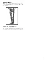
Page 7: ...d the power cord around the cord storage hook on the handle shaft and both of the handle grips as shown CLEAN UP AND STORAGE After being used your floor machine can be wiped clean with a soft damp cloth and should be stored in a clean dry place ...

Page 8: ...d by improper unreasonable or neglect use or abuse while in possession of the purchaser are likewise excluded from this warranty If repair is done on your equipment by anyone other than those designated as an authorized Warranty Center THE MANUFACTURER at its sole option may determine that this warranty will not apply and the reimbursement for such repair will not be made PROCEDURE TO BE TAKEN TO ...

Reviews: