L
aser distance sensor user manual
- 4 -
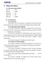
4. Using instructions
4.1 Cable connecting definitions
Red line
—— VCC
Black line
—— PGND
Yellow line
—— TX
Green line
—— RX
White line
—— DGND
4.2 Operating Steps
4.2.1 Connection
Connect the sensor to a serial port of computer (or other device which
has serial ports), then connect to a power port of adapter with special data cable.
4.2.2 Single Trigger Measuring Mode
4.2.2.1 Send a command “O” (ASCII) by computer to turn on the sensor.
Then sensor will emit a laser beam and prepare for working, and return the data
“ - - - - ” (ASCII) to the serial interface.
4.2.2.2 Send a command “O” (ASCII) again to the sensor to start to
measure distance. The sensor will return the measured data like “ XXXXXX” (ASCII)
to the serial interface and turn off laser beam when it finished a single
measurement.
4.2.2.3 Send a command “U” (ASCII) to turn off the sensor.
4.2.3 Continuous Measuring Mode
4.2.3.1 Send a command “O” (ASCII) by computer to turn on the sensor.
Then the sensor will turn on the laser and prepare for working, return the data “ -
- - -” (ASCII)to the serial interface.
4.2.3.2 Send a command “C” (ASCII) to the sensor. The sensor will begin
to measure continuously after 2 seconds when it got the command, and return
the data continuously like “ XXXXXX” (ASCII).
If the sensor couldn’t get any available data, it will return “ - - - -” to the
serial interface.
4.2.3.3 Send a command “U” (ASCII) to turn off the whole sensor
(include both of laser unit and measuring unit).


