27
Other Operations
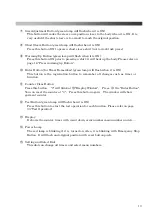
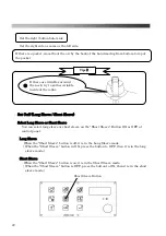
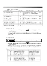
How to Reset Emergency Stop (Safety Error)
In case the Emergency Stop Button or Safety Guard at the Front Press/Shoulder Press/Tuck
Press is activated, the buzzer goes off and all of the operations will stop working. All the
presses (Shoulder/Body/Tuck) begin to open and the display window will show an error.
How to Release
・
In case of Pressing Emergency Stop Button:
Release the lock by turning the button to the right. Press the Reset Button.
The Emergency Stop cannot be released unless the Reset Button is pressed.
・
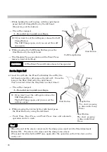
In case of Pressing Each Safety Guard:
Press the Reset Button, then the machine will start to work
※
In case of the front press not being at the original position, it will then move to its
original position. (“A03” will be displayed during the move
About the Cover Counter
The Cover Counter was created to make it easy for the customer to know when to change the
cover and insure the proper finish quality. If the cover counter exceeds 25,000 times, there
will be an error displayed (EC1) when the power is turned on, and the machine will not
start.
※
THEREFORE, AFTER CHANGING THE COVER, ALWAYS RESET THE COUNTER
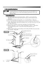
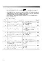
Please use the following instructions when resetting the cover counter.
①
After changing the cover, turn the machine on and press the blue reset button for an
extended time. Doing this will cancel the buzzer and error.
It is possible to use the machine after completing this step. However, if the counter
is not reset, the reset button must be pressed again the next time the machine is
turned on.
②
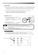
Press " Test” Button on the control panel.
→
The display will show
.
③
Turn the Set/ Select Dial until is displayed. Press the "Enter" Button.
→
The display will show
.(Number is a pro forma amount.)
④
Press "Counter Clear” Button on the control panel.
→
The display will show , and the 0 will start flashing.
⑤
Press "Enter" Button on the control panel.
→
The display will show a solid 0 with no flashing.
The Reset is finished.
⑥
Press the “Test" Button once more to return to
standard operation.
②
Display Window
④
⑤
③
⑥
Caution
Summary of Contents for LP-570E-V2
Page 54: ...54 Motor Operation Diagram 1 Motor Operation Diagram REV 4...
Page 56: ...56 Air Piping 1 2 Air Piping 1 REV 3 3DLP570E V2 052 2...
Page 58: ...58 Air Piping 2 3 Air Piping 2 REV 3 3DLP550J V2 053 6...
Page 60: ...60 Air Piping 3 4 Air Piping 3 REV 3 3DLP550J V2 054 6...
Page 62: ...62 Steam Piping 5 Steam Piping REV 3 3DLP570E V2 055 1...
Page 64: ...64 Control Box Switch Diagram 6 Control Box Switch Diagram REV 3 3DLP550J V2 056 6...
Page 66: ...66 Cover Diagram 7 Cover Diagram REV 3 3DLP570E V2 057 3...
Page 69: ......
Page 70: ......
Page 71: ......
Page 72: ......
Page 73: ......
Page 74: ......
Page 75: ......
Page 76: ...LP 570E V2X Rev 6 2019 6 1 2 B...

