36
Service Menu
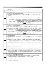
Press the Service Button (BP1) on the main circuit board in the control box; you can check the
“Input Test”, “Output Test”, “Volume Control”, “Dip Switch Set” and “Timer Setting”.
Furthermore, you can reset all the settings to factory standard and check the software
version.
■
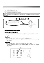
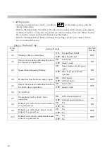
Here is an explanation for the Service Button Location, all buttons and functions to use for the
operation of the service menu.
①
Service Button
Push this button, you will see “In1” on display and ready to use service menu.
②
Counter Clear Button
This is the Return Button on service menu.
③
Long Timer Button
It is used on Input Test 2. Button lamp is ON at input which is ON, and the lamp is OFF at
input which is OFF. It is useful to check for possible wire disconnection problem.
④
Enter Button
This is the confirmation button for menu which is selected, and to confirm details of a setting
change.
⑤
Setting & Select Dial
This is a dial for menu select and item select on the service menu.
Counterclockwise: item forward, and number up on setting.
Clockwise: item return, and number down on setting.
Do not touch anywhere due to the potential danger when you open the
control box.
Main Circuit Board
Control Panel
②
④
⑤
③
①
WARNING
The initial setting will be changed without prior notice at the time of model changes.
Caution
Summary of Contents for LP-570E-V2
Page 54: ...54 Motor Operation Diagram 1 Motor Operation Diagram REV 4...
Page 56: ...56 Air Piping 1 2 Air Piping 1 REV 3 3DLP570E V2 052 2...
Page 58: ...58 Air Piping 2 3 Air Piping 2 REV 3 3DLP550J V2 053 6...
Page 60: ...60 Air Piping 3 4 Air Piping 3 REV 3 3DLP550J V2 054 6...
Page 62: ...62 Steam Piping 5 Steam Piping REV 3 3DLP570E V2 055 1...
Page 64: ...64 Control Box Switch Diagram 6 Control Box Switch Diagram REV 3 3DLP550J V2 056 6...
Page 66: ...66 Cover Diagram 7 Cover Diagram REV 3 3DLP570E V2 057 3...
Page 69: ......
Page 70: ......
Page 71: ......
Page 72: ......
Page 73: ......
Page 74: ......
Page 75: ......
Page 76: ...LP 570E V2X Rev 6 2019 6 1 2 B...

