37
■
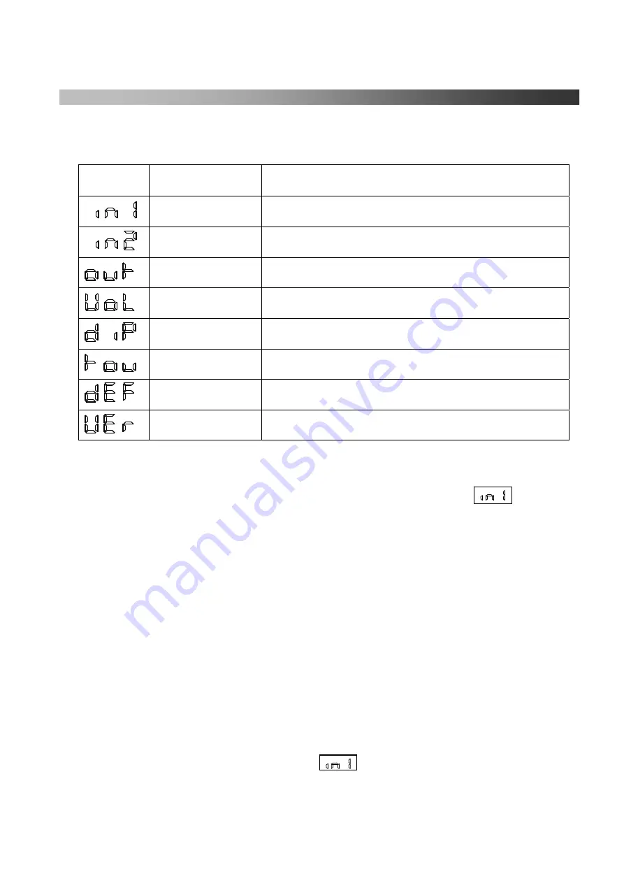
Service Menu List
(Please read the following list for the details which is written as Service
Menu Explanation.
)
Display Meaning
Function
in1
For “input test 1”
in2
For “input test 2”
out
For “output test”
VoL
For volume control setting
diP
For dip switch select
tou
For timer change which is shown the number on display
dEF
For reset all program to standard of factory shipping
(default)
VEr
For showing current version number of program
■
How to operate
1.
Press the “Service Button” on main circuit board No, 1
→
It is shown
on display.
2.
Dial with “Setting & Select” knob No.5 and select the service menu.
3.
When you see the menu which you want to select, press the “Enter” button No.4.
4.
Operate referring to one of the “Service Menu Explanation” which you are looking for.
5.
When you finish all of the set up, press the “Counter Clear” button No.2 to return to
the original position. (Even if you don’t push the counter clear button, it will return to
the original position automatically.)
■
Service Menu Explanation
1.
In1
(
Input Test 1
)
・
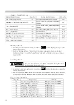
According to instruction 1, you can see on the display, please push the “Enter”
button No.4. If you push the input button / pedal (reference to chart 1), the number will
be shown.
Summary of Contents for LP-570E-V2
Page 54: ...54 Motor Operation Diagram 1 Motor Operation Diagram REV 4...
Page 56: ...56 Air Piping 1 2 Air Piping 1 REV 3 3DLP570E V2 052 2...
Page 58: ...58 Air Piping 2 3 Air Piping 2 REV 3 3DLP550J V2 053 6...
Page 60: ...60 Air Piping 3 4 Air Piping 3 REV 3 3DLP550J V2 054 6...
Page 62: ...62 Steam Piping 5 Steam Piping REV 3 3DLP570E V2 055 1...
Page 64: ...64 Control Box Switch Diagram 6 Control Box Switch Diagram REV 3 3DLP550J V2 056 6...
Page 66: ...66 Cover Diagram 7 Cover Diagram REV 3 3DLP570E V2 057 3...
Page 69: ......
Page 70: ......
Page 71: ......
Page 72: ......
Page 73: ......
Page 74: ......
Page 75: ......
Page 76: ...LP 570E V2X Rev 6 2019 6 1 2 B...


