background image

1

2

2

2

4

3

5

6

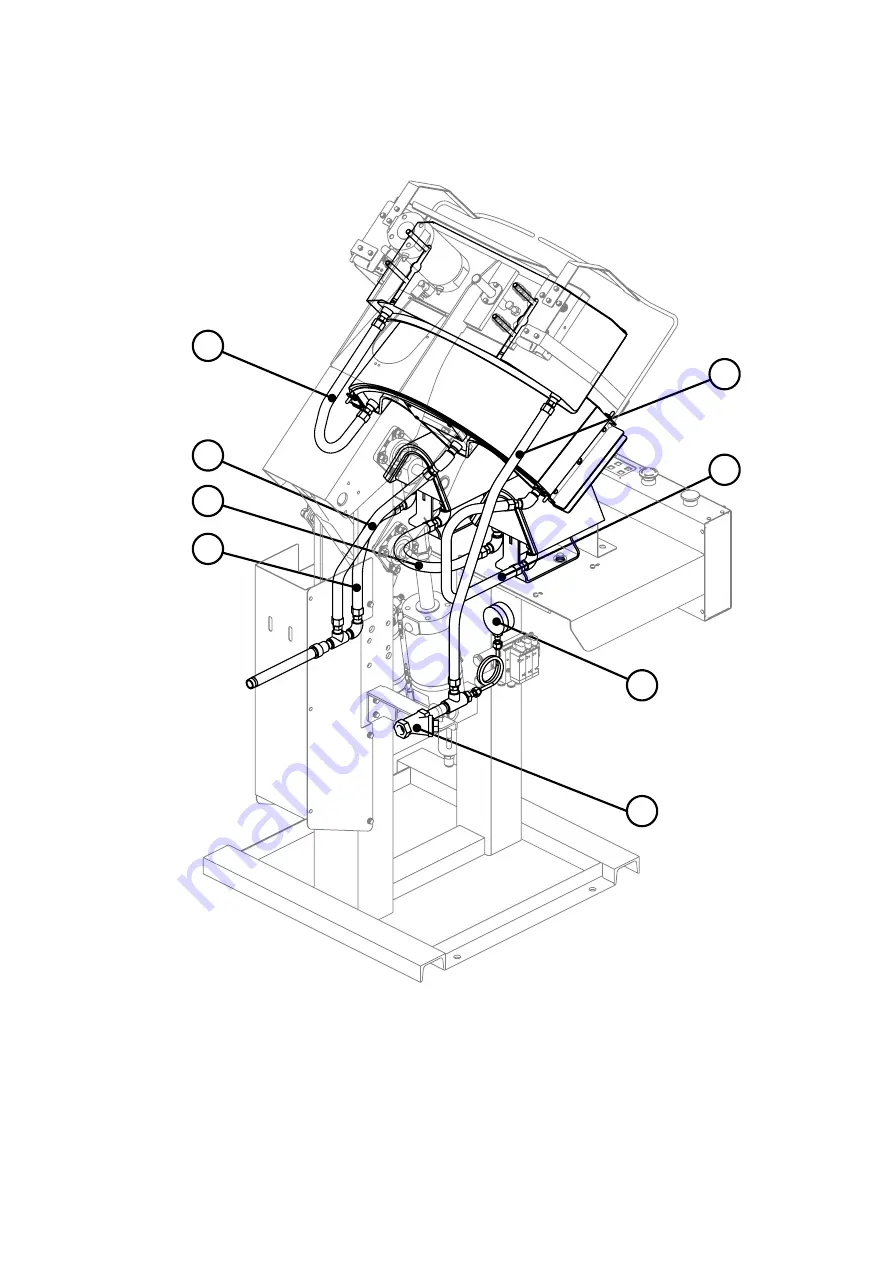
① Flexible Hose   : 3/8×650L(B)
② Flexible Hose   : 3/8×470L(B)
③ Flexible Hose   : 3/8×350L(B)
④ Flexible Hose   : 3/8×250L(B)
⑤ Pressure Gauge  : AMT7/16 60φ 1.6MPa
⑥ Y Strainer          : FCKY4-G3 15A 80Mesh 

Steam Piping Diagram

Summary of Contents for LP-660E-V2

Page 1: ...For your safety please read this Instruction Manual thoroughly If at any time you have any questions please do not hesitate to contact us Instruction Manual LP 660E V2...

Page 2: ......

Page 3: ...pressure 0 6Mpa Steam pressure 0 6Mpa Air Pipe 3 8B Steam Pipe 1 2B Weight 200kg Dimensions Width Depth Height 740 970 1610 mm Max Welcome Thank you for choosing our Single Collar Cuff Press LP 660E V...

Page 4: ...Select finish time 15 5 Set the shirt 16 6 After operation is over 17 About the Collar Cuffs Button 17 Other Operations 18 How to Reset Emergency Stop 18 About a Cover Counter 18 Cover Pad Change Inst...

Page 5: ...is used to notify of unspecified prohibition Shock Hazard This is used to note the Possibility of electric shock in certain circumstances Prohibition of Dismantling This is used to note the possibilit...

Page 6: ...dismantle the machine by yourself It may cause electric shock injury fire or an accident Shock Hazard Don t touch the electric plug or switch It may cause an electrical shock Shock Hazard Parts must...

Page 7: ...fferent electrical supply Cleaning Both the main power switch and the breaker should be off when cleaning It may cause electrical shock without power off Check and cleaning An electric plug and an ele...

Page 8: ...e Area DANGER Control box has terminals with lethal voltage Only qualified person can open the cover Shut off the power before opening the cover Ignoring this warning will result in serious injury or...

Page 9: ...The machine has some moving areas along any portions Keep your hands away from moving area during operation Before starting check up or maintenance turn off the air and power first Ignoring this warn...

Page 10: ...e Area CAUTION The machine has hot surfaces which get extremely hot during operation Never touch hot surfaces during and for 30 minutes after the steam has been turned off Ignoring this warning may re...

Page 11: ...hazard Keep hands away from the machine Do not touch while in operation Press surface is HOT Do not touch press head piping and its surrounding area Be careful There is a high risk of catching your f...

Page 12: ...it Collar Press Head Upper Press Right Safety Bar Cuff Press Head Middle Press Cuff Table Steam Gauge Main Switch Steam Inlet Electric Box Steam Outlet Regulator Air Inlet Solenoid Valve Control Panel...

Page 13: ...ol panel part Left Start Button When you push this button and the right start button simultaneously the machine presses clothes The pressing time can be selected by pressing either the set long timer...

Page 14: ...ill turn on The setting can be changed using this button 1 The shirt will be pressed only for the period of time shown on the short timer A green light will appear the pressing time will be displayed...

Page 15: ...button 0 will blink at Display Window Press the Enter Button You can reset the counter at 0 Press this button again The window will show garment counter Enter Button The light turns green when the bu...

Page 16: ...does not reach its standard level set the air pressure properly following the procedure below Check Point Check compressor if the main air pressure does not reach 0 6MPa even after the above adjustmen...

Page 17: ...ar on the upper right side of the selected button Press the Enter Button to save the setting The last mode Short or Long saved before turning the power off will appear as default setting next time the...

Page 18: ...completely down otherwise it will release the press head Set the collar on the collar press table See on right Press both start buttons at once Collar Press Head will come down and press the collar Do...

Page 19: ...ton off on the control panel The green lamp will turn off when you do it is possible to press shirts with only the upper press Therefore areas like the placket of the shirt can be easily processed Pre...

Page 20: ...eeds 10 000 times there will be an error displayed EC1 when the power is turned on and the machine will not start THEREFORE AFTER CHANGING THE COVER ALWAYS RESET THE COUNTER Please use the following i...

Page 21: ...h start buttons without shirt on the machine Figure 1 Turn OFF the power supply after setting the air pressure to 0 MPa See page 15 Remove the guard plate in front of middle press head Figure 2 Loosen...

Page 22: ...dle press so that a color silicone sponge side may be turned down and a stainless rod long may become the front Hook the stainless rod to the rod holder on the left side from the front view Then hook...

Page 23: ...both of wing bolts equality It will be pulled the color cover gradually Install without any wrinkles That s all for the cover change Guard plate Fixed screw 3 Pcs Stainless rod Wing bolts Clockwise T...

Page 24: ...sponge and cuffs spring felt pad 10 then install them to cuffs cover Place the cuff cover on the cuff table and then tight it the cover will be fixed on the press table Make sure no wrinkles on the su...

Page 25: ...This button functions as return button in service menu Short Button Lamp of this button is turned ON OFF when test operation is ON OFF in Input test Enter Button If this button is pushed selected men...

Page 26: ...3 Press Enter Button to start the selected Service Menu 4 Work or set on the selected Menu See Service Menu Explanation for further details 5 After completion of the Menu press Counter Clear Button a...

Page 27: ...ss when is displayed push Enter button After display number table3 is selected with Set Select Dial when Enter button is pushed present setting time is displayed Setting time is changed with Set Selec...

Page 28: ...is selected as the initial setting ON OFF While the power is ON Collar Mode is selected as the initial setting 6 tou Time setting in display window After 1 2 process when is displayed push Enter butt...

Page 29: ...Procedure 1 and 2 and shows up Press Enter Button to select Turn Set Select Dial and select the number as seen in Chart 6 The Test Mode will turn on When test is done press Counter Clear button Return...

Page 30: ...eft safety bar 2 Switch XE02 of left safety bar is pushed 3 1 When pushing the safety bar by hand if the bar is released the error mark will disappear and the display will appear Check that the safety...

Page 31: ...ot display or S4 does not appears on the display panel There is a problem with the cylinder sensor Check the sensor s wiring has not become disconnected etc If no problem is found then the cylinder se...

Page 32: ...with the valve Check valve and air pressure E25 1 Close upper press arm sensor SQ06 error 2 When a power supply is turn on or at the time of upper press start upper press cylinder arm sensor turns on...

Page 33: ...ace the controller E98 1 Display board external input error From software version 2 02 onward 2 Input of the display board failed to work properly 3 1 Confirm whether or not the entry connector doesn...

Page 34: ...ur Sankosha equipment please read and comprehend carefully this Daily Check Manual thoroughly before operation Keep this manual in a safe place for easy access at all times The Checking cycle will dif...

Page 35: ...utomatic drain function works properly at the Regulator Mist Separator The drain is automatically discharged when the quantity of the drain reaches over half of the drain case If the drain cannot be d...

Page 36: ...e deposit from burning and to keep ironing quality 6 Emergency Stop Button Figure 5 Press the emergency stop button right safety bar and left safety bar to ensure that the machine stops Start Operatio...

Page 37: ...ap 5 Cover 6 Press surface 7 Emergency stop No Item 16 17 18 19 20 21 22 23 24 25 26 27 28 29 30 31 1 Air Pressure 2 Regulator Mist Separator 3 Steam Pressure 4 Steam Trap 5 Cover 6 Press surface 7 Em...

Page 38: ...36...

Page 39: ...Spare Parts List Index 1 Front Diagram 2 Rear Diagram 3 Steam Piping 4 Cover Diagram 37...

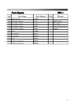
Page 40: ...1 Front Diagram REV 1 38...

Page 41: ...I171 1 EMG SW Red 103 Push Button Switch 21I170 1 Reset Blue 104 Push Button Switch 21I169 2 Right left start Green 105 Push Button Switch 21I085 2 EMG Bar 106 Knob 21D006 1 107 Panel Sheet 20U111 1 1...

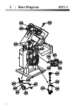
Page 42: ...2 Rear Diagram REV 1 201 202 207 203 204 205 205 206 208 209 210 211 212 213 214 215 216 217 218 40...

Page 43: ...19 1 207 Speed Controller C1G015 2 Silenser B0W014 1 Middle Press Arm Cylinder Packing Set B6H045 1 209 Knuckle Joint B6A020 1 210 Speed Controller C1A056 1 Cylinder Sensor B5A015 1 Sensor Band B5C002...

Page 44: ...3 Steam Piping REV 1 42...

Page 45: ...eam Piping REV 1 No Part Name Part number Q ty Remark 301 Flex Hose A6B022 1 302 Flex Hose A6B016 3 303 Flex Hose A6B015 1 304 Flex Hose A6B021 1 305 Y Type Strainer J2M009 1 306 Steam Gauge J0A003 1...

Page 46: ...4 Cover Diagram REV 1 44...

Page 47: ...2 Cuff Spring Felt Pad 10mm S1C061 2 403 Cuff Cover Right S1C059 1 404 Cuff Cover Left S1C060 1 405 Collar Silicon Sponge 30 S1C058 1 406 Collar Spring Felt Pad 10mm S1C056 1 407 Collar Cover S1C055 1...

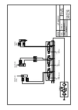
Page 48: ...Diagram Sensor Diagram Electric Connection Diagram 1 4 4 4 Steam Piping Diagram All Air System 46...

Page 49: ...01 Emergency Button SB06 Right Safety Switch SB03 Left Start Button SB04 Right Start Button SQ01 Middle Press End Sensor SQ03 Upper Press Arm End Sensor SQ02 Upper Press Arm Sensor SB05 Left Safety Sw...

Page 50: ......

Page 51: ......

Page 52: ......

Page 53: ......

Page 54: ...1 2 2 2 4 3 5 6 Flexible Hose 3 8 650 Flexible Hose 3 8 470 Flexible Hose 3 8 350 Flexible Hose 3 8 250 Pressure Gauge AMT7 16 60 1 6MPa Y Strainer FCKY4 G3 15A 80Mesh Steam Piping Diagram...

Page 55: ...N K O S H A DATE MODEL TYPE ALL AIR SYSTEM LP660A V2 Middle Press Arm Cylinder Upper Press Arm Cylinder Upper Press Cylinder YV02 Close Middle Press Arm YV03 Close Upper Press Arm YV04 Close Upper Pre...

Page 56: ...LP 660E V2 X Rev 2 2019 11 Sankosha Manufacturing Co Ltd 988 Kanoya Cho Hachioji Tokyo 193 0815 JAPAN T e l 81 42 621 1181 F a x 81 42 620 0751 URL http overseas sankosha mfg com Distributor...

Reviews: