12
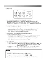
Control Box
①
Main Switch
Pushing the black button, the machine will turn ON.
②
Emergency Stop Button
When you push the emergency stop button, the machine will return to it’s original position, during any
process, safely. “E1”will be displayed and when returning to the original operation, rotate the button
clockwise and the button will be released and “--1”will appear on the display. Then push the reset
button. The display will then return to the normal count display.
③
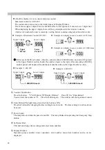
Control Panel
Finish mode and timer setup can be changed. Refer to 13-page "control panel part".
④
Left Start Button
When you push this button and the right start button simultaneously, the machine press head closes.
The pressing time can be selected by pressing either the set long timer button / short timer button on
control panel.
⑤
Right Start Button
When you push this button and left start button simultaneously, the machine press head closes.
The pressing time can be selected by pressing either the set long timer button / short timer button on
control panel.
⑥
Reset Button
This button has 3 functions depending on the process.
1.
To return frame to original position after power is turned on.
2.
To return to normal operation after emergency stop button or safety bar has been worked.
3.
To return to the original position after the stop button has been pressed.
①
⑤
⑥
②
④
③
Summary of Contents for LP-690E-V3
Page 2: ......
Page 11: ...9...
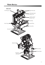
Page 13: ...11 Main Device Main Unit...
Page 41: ...39 Spare Parts List Index 1 Front Diagram 2 Rear Diagram 3 Steam Piping 4 Cover Diagram...
Page 42: ...40 Front Diagram 1 Front Diagram REV 1 3DLP690J V3 051 1...
Page 44: ...42 Rear Diagram 2 Rear Diagram REV 1 3DLP690J V3 052 1...
Page 46: ...44 Steam Piping 3 Steam Piping REV 1 3DLP690J V3 053 1...
Page 48: ...46 Cover Diagram 4 Cover Diagram REV 1 3LP690J V3 054 1...
Page 52: ......
Page 53: ......
Page 54: ......
Page 55: ......
Page 57: ......

