13
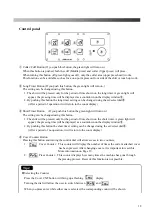
Control panel
①
Collar
・
Cuff Button (If you push this button, the green light will turn on.)
When this button is pushed, both the cuff (Middle press) and collar (Upper press) will press.
When turning this button off (green light goes off), only the collar area (upper press head) works.
This function can be available such as for a one-point press on front side of the shirt or touch up work.
②
Long Timer Button (If you push this button, the green light will turn on.)
The setting can be changed using this button.
1. The shirt will be pressed only for the period of time shown on the long timer. A green light will
appear, the pressing time will be displayed as a countdown on the display window
⑨
.
2. By pushing this button the long timer setting can be changed using the set/select dial
⑧
.
(After a period of operation it will return to the count display)
③
Short Timer Button. (If you push this button the green light will turn on.)
The setting can be changed using this button.
1. The shirt will be pressed only for the period of time shown on the short timer. A green light will
appear, the pressing time will be displayed as a countdown on the display window
⑨
.
2. By pushing this button the short timer setting can be changed using the set/select dial
⑧
.
(After a period of no operation, it will return to the count display)
④
Cover Counter Button
Pressing this button and turning the control dial will allow access to two counters,
1.
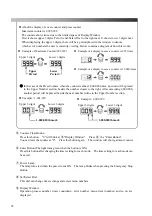
Cover Counter
:
This counter will display the number of times the current attached cover
has been pressed. After changing covers, it is important to reset this.
More information on Page 19.
2.
Press Counter
:
This counter displays how many times the machine has gone through
the pressing process. Reset of this function is not possible.
Selecting the Counter
Press the Cover CNT button will bring up a flashing
display.
Turning the dial will allow the user to switch between and
、
When you press enter while either one is selected, the corresponding count will be shown.
①
④
②
⑤
③
⑥
⑦
⑧
⑨
Tips
!
Summary of Contents for LP-690E-V3
Page 2: ......
Page 11: ...9...
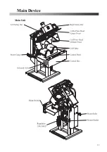
Page 13: ...11 Main Device Main Unit...
Page 41: ...39 Spare Parts List Index 1 Front Diagram 2 Rear Diagram 3 Steam Piping 4 Cover Diagram...
Page 42: ...40 Front Diagram 1 Front Diagram REV 1 3DLP690J V3 051 1...
Page 44: ...42 Rear Diagram 2 Rear Diagram REV 1 3DLP690J V3 052 1...
Page 46: ...44 Steam Piping 3 Steam Piping REV 1 3DLP690J V3 053 1...
Page 48: ...46 Cover Diagram 4 Cover Diagram REV 1 3LP690J V3 054 1...
Page 52: ......
Page 53: ......
Page 54: ......
Page 55: ......
Page 57: ......

