24
④
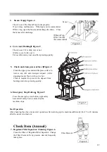
Insert the cuff silicone (small) into the pouch of the double felt pad (small). (Figure-3)
Rough surface of the silicone should be facing that side like Figure-4.
Put the silicone deep inside.
There should be about 8mm gap. (Figure-4)
⑤
Install the pad that combined at process
④
to the machine.
Insert the screws through the hole of pad, and fix the metal bracket.
⑥
Put cuff silicone (big) on the press in the center position.
Rough surface of the silicone should be facing that side like Figure-5.
Put cuff double felt pad (big) on cuff silicone (big) in center position.
Thin surface of the felt is facing up, and install double felt pad (big) over double felt pad (small).
Insert the screws through the hole of pad, and fix the metal bracket.
Figure-5
Figure-3
Figure-4
Summary of Contents for LP-690E-V3
Page 2: ......
Page 11: ...9...
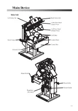
Page 13: ...11 Main Device Main Unit...
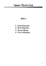
Page 41: ...39 Spare Parts List Index 1 Front Diagram 2 Rear Diagram 3 Steam Piping 4 Cover Diagram...
Page 42: ...40 Front Diagram 1 Front Diagram REV 1 3DLP690J V3 051 1...
Page 44: ...42 Rear Diagram 2 Rear Diagram REV 1 3DLP690J V3 052 1...
Page 46: ...44 Steam Piping 3 Steam Piping REV 1 3DLP690J V3 053 1...
Page 48: ...46 Cover Diagram 4 Cover Diagram REV 1 3LP690J V3 054 1...
Page 52: ......
Page 53: ......
Page 54: ......
Page 55: ......
Page 57: ......


