31
Trouble Shooting
◎
During the operation, an error number shows up at the Display Window on the Operation Panel if
something is wrong. Check below List, and take the necessary action.
Call your dealer or Sankosha if the normal operation does not resume.
If any of [
EEE
]
,
[
EE1
]
,
[
EE2
]
,
[
EE3
]
,
[
EE4
]
,
or [
EE5
] shows up,
Turn the power OFF and turn the power ON again
more than 5 seconds later
.
Call your dealer or Sankosha if the normal operation does not resume.
Error
number
(1)
Error description
(2)
Error detail
(3)
Check contents
E1
1. Emergency stop button
2. Emergency stop button is pushed.
3. (1) Turn Emergency stop button clockwise to release lock and the display
(―
―
1
)
will appear.
Push reset button to return to normal condition.
(2) If error is displayed although emergency stop button lock is released, this is button problem.
Check the emergency button itself and it’s wiring.
E2
1. Left safety bar
2. Switch (XE02) of left safety bar is pushed.
3. (1) When pushing the safety bar by hand if the bar is released the “error “ mark will disappear and
the display
(―
―2)
will appear. Check that the safety bar is not caught anywhere.
(2) If error (E2) is displayed and the safety bar is not being pushed there is a problem with the
safety bar switch or wiring.
E3
1. Right safety bar
2. Switch (XE03) of right safety bar is pushed.
3. (1) When pushing the safety bar by hand if the bar is released the “error “ mark will disappear and
the display
(―
―3)
will appear. Check that the safety bar is not caught anywhere.
(2) If error (E3) is displayed and the safety bar is not being pushed there is a problem with the
safety bar switch or wiring.
It is extremely dangerous in Control Box.
Do not touch anywhere unless otherwise specified.
WARNING
Please see the “Sensor Diagram” on the last page for the location of each cylinder
sensor or button.
You can make sure of the cylinder sensor or button through “Input Test 1” in
Service Menu.
(Page 27)
Information
CAUTION
Summary of Contents for LP-690E-V3
Page 2: ......
Page 11: ...9...
Page 13: ...11 Main Device Main Unit...
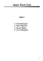
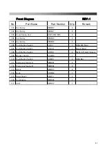
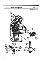
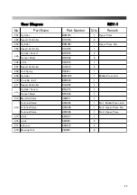
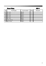
Page 41: ...39 Spare Parts List Index 1 Front Diagram 2 Rear Diagram 3 Steam Piping 4 Cover Diagram...
Page 42: ...40 Front Diagram 1 Front Diagram REV 1 3DLP690J V3 051 1...
Page 44: ...42 Rear Diagram 2 Rear Diagram REV 1 3DLP690J V3 052 1...
Page 46: ...44 Steam Piping 3 Steam Piping REV 1 3DLP690J V3 053 1...
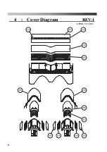
Page 48: ...46 Cover Diagram 4 Cover Diagram REV 1 3LP690J V3 054 1...
Page 52: ......
Page 53: ......
Page 54: ......
Page 55: ......
Page 57: ......


