40
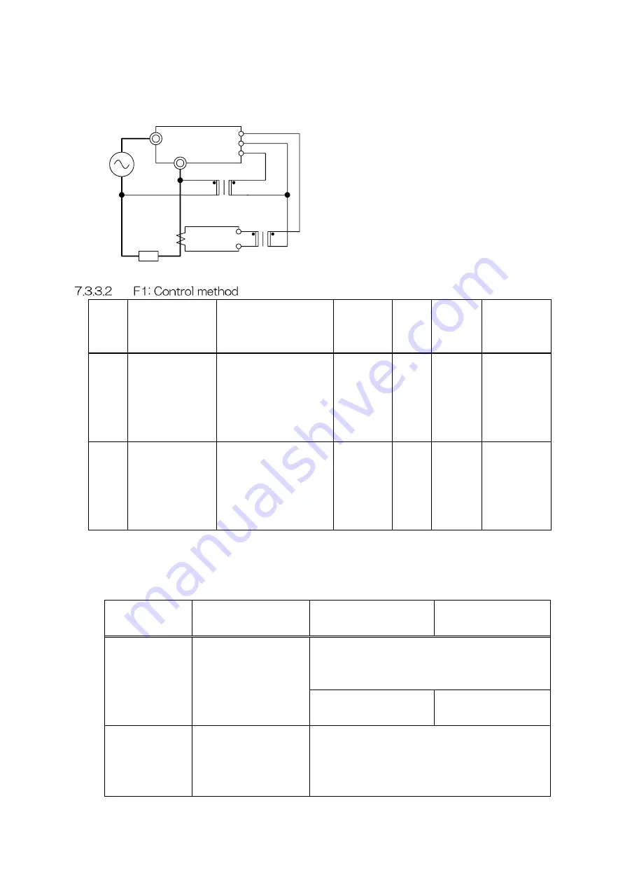
(4) Set the rated voltage to that specified for the primary side of the external PT (optional
item). (The value indicated with ▲▲ in the following figure.)
UG1
L
K
L
k
l
K
L
k
l
K
■■A:5A
Main circuit CT
5A:0.1A
External CT
Load
External PT
K
▲▲V
0V
3V
0V
V1
D1
I1
Code
Function name
Setting range
Increment
Unit
Default
value
Changeable
during
operation
F100
Waveform
control method
0: Phase control
1: Intermittent cycle
control
2: Continuous cycle
control
–
–
0
✓
F101
Temperature
controller type
0: 4 to 20 mA
(1 to 5 VDC)
1: 0 to 5 VDC
2: Two-position
control
–
–
0
✗
F100: Waveform control method
Select the waveform control method.
The following three methods are available: phase control, intermittent cycle control, and
continuous cycle control. Each has the following characteristics.
Phase control
Intermittent cycle
control
Continuous cycle
control
Overview
The phase is
controlled once every
half cycle using the
effective value.
The number of ONs in a cycle during a
specified period is controlled with the effective
value.
Period: Automatically
adjusted
Period: Fixed at an
arbitrary value
Load to apply
Resistance load,
inductive load,
transformer primary
control
Resistance load
(Customized product: Transformer primary
control)
External CT (optional item)
Main circuit CT (prepared by user)
Summary of Contents for CALPOTE UG Series
Page 94: ...94 APPENDIX B PANEL TRANSITION DIAGRAM...
Page 96: ...MEMO...


