75
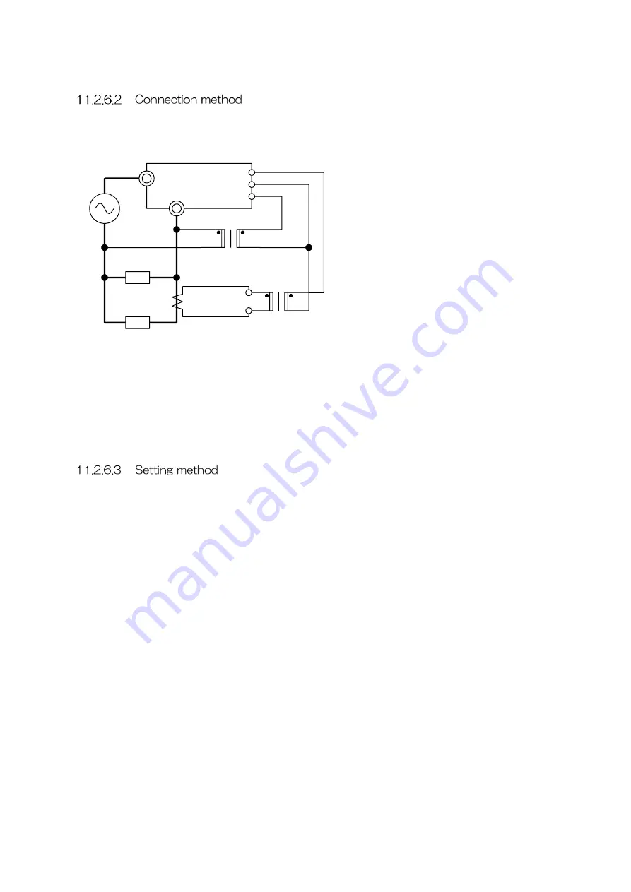
To use this function, the heaters, main circuit CT, external CT, and external PT need to be
connected differently from the standard connection. Connect these items according to the
following diagram.
UG1
L
K
L
k
l
K
L
k
l
K
Heater A
Heater B
K
▲▲V
0V
3V
0V
V1
D1
I1
■■A:5A
Main circuit CT
5A:0.1A
External CT
External PT
※
Select the main circuit CT by referring to the rated current of the unit. It is not necessary to
take into consideration heaters divided into two groups when selecting the main circuit CT.
※
It is recommended to connect at least two heaters to the A side. The feedback control,
which uses the external CT, cannot be performed correctly if all heaters connected to the
A side are disconnected. (The signal continues to be output via the heaters on the B side.)
The related parameters are shown below.
F401: Heater disconnection detection function
Select [3: Enable highly functional version] to enable the highly functional version function.
When the function needs to be temporarily disabled for test operation or other purposes,
select [1: Disable highly functional version].
※
The standard version described in the previous section is also available with this
function. Be sure to set the value to [3: Enable highly functional version] or [1: Disable
highly functional version] when heaters are divided into two groups for the highly
functional version. Failure to do so may cause incorrect feedback control, leading to
overcurrent.
F402: Heater A count
Specify the number of heaters connected in parallel. The heater A count refers to the
number of heaters connected to the side to which the main circuit CT is connected, as
shown in the connection diagram.
F403: Heater B count
Specify the number of heaters connected in parallel. The heater B count refers to the
number of heaters connected to the side without the main circuit CT, as shown in the
connection diagram.
Summary of Contents for CALPOTE UG Series
Page 94: ...94 APPENDIX B PANEL TRANSITION DIAGRAM...
Page 96: ...MEMO...


