33
3.5.2 FUSING
The 200AP unit is equipped with an input switch and does not have and input circuit
breaker for protection. It is the responsibility of the user to provide proper fuse protection for the
welding power source. Failure to do so will void the warranty. The installer should reference the
table above to select a suitable fuse for the input voltage of the installation location.
NOTE:
Maximum fuse size should be such that the fuse value not be more than 200 percent
of the rated input amperage of the welding power source.
(Based on Article 630, National Electrical Code).
3.5.3 ELECTRICAL INPUT CONNECTIONS
•
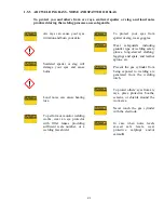
DO NOT TOUCH live electrical parts.
•
SHUT DOWN welding power source, disconnect input power employing lockout/tagging
procedures. Lockout/tagging procedures consist of padlocking line disconnect switch in
open position, removing fuses from fuse box, or shutting off and red-tagging circuit
breaker or other disconnecting device.
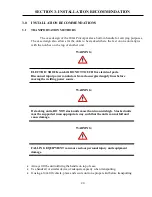
WARNING:
ELECTRIC SHOCK can kill; a SIGNIFICANT DC VOLTAGE is present after
removal of input power until the internal components have time to discharge.
A line disconnect switch provides a safe and convenient means to completely remove
all electrical power from the welding power supply whenever necessary to inspect or service
the unit.
Summary of Contents for SANARG 200AP
Page 2: ......
Page 4: ......
Page 8: ......
Page 24: ...24 PAGE LEFT INTENTIONALLY BLANK ...
Page 35: ...35 Figure 3 2 Electrical Input Connections 200AP ...
Page 60: ...60 PAGE LEFT INTENTIONALLY BLANK ...
Page 66: ...66 PAGE LEFT INTENTIONALLY BLANK ...
Page 79: ...79 PAGE LEFT INTENTIONALLY BLANK ...
Page 80: ...80 10 1 INTERCONNECT DIAGRAM 200AP ...
Page 81: ...81 ...
Page 82: ...82 10 2 EXPLODED VIEW 200AP ...
Page 83: ...83 ...
Page 84: ...84 PAGE LEFT INTENTIONALLY BLANK ...
Page 89: ...PAGE LEFT INTENTIONALLY BLANK ...


