background image

80 


10.1


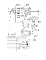
INTERCONNECT DIAGRAM 200AP 


Summary of Contents for SANARG 200AP

Page 1: ...SanRex SANARG 200AP AC DC INVERTER ARC WELDER Operators Manual Version No B Issue Date JUN 12 2019 Manual No K00A0316900 ...

Page 2: ......

Page 3: ...cated solely to the safety of you and others in the work area It is highly recommended that this information be reviewed and that this manual be kept in a secure but accessible location for reference of these import safety and well being notices Remember the number one requirement in performing any job is safety Sansha Electric of Osaka Japan and its SanRex brand name of products has specialized i...

Page 4: ......

Page 5: ...e product SECTION 3 INSTALLATION RECOMMENDATIONS Describing the transportation working environment electrical hook up with consideration for grounding and high frequency interference Also input power connections and specifications SECTION 4 OPERATOR CONTROLS DIMENSIONS AND OUTLINE Included in this section is a sequence of operation welding process selection welding model 200AP attributes and model...

Page 6: ... 27 2 4 1 200AP V A OUTPUT CURVES 27 2 5 FUNCTIONAL BLOCK DIAGRAM 28 3 0 INSTALLATION RECOMMENDATIONS 29 3 1 TRANSPORTATION METHODS 29 3 2 ENVIRONMENT 30 3 3 MACHINE GROUNDING HIGH FREQUENCY INTERFERENCE 30 3 3 1 GROUNDING 30 3 3 2 HIGH FREQUENCY INTRODUCTION 30 3 3 3 HIGH FREQUENCY INTERFERENCE 31 3 4 LOCATION 32 3 5 ELECTRICAL INPUT CONNECTIONS REQUIREMENTS 32 3 5 1 INPUT POWER 32 3 5 2 FUSING 3...

Page 7: ...4 6 4 HF TIG SEQUENCE 55 6 4 1 STANDARD MODE 55 6 4 2 SLOPE MODE 55 6 4 3 REPEAT MODE 55 6 4 4 SPOT MODE 56 7 0 VOLTAGE REDUCTION DEVICE VRD 57 7 1 VRD SPECIFICATIONS 57 7 2 SWITCHING VRD ON Off 57 8 0 TROUBLE SHOOTING 61 8 1 POWER SOURCE PROBLEMS 61 8 2 POWER SOURCE ERROR CODES 63 9 0 ROUTINE MAINTENANCE 67 9 1 OPENING THE ENCLOSURE 68 10 0 PARTS LIST 200AP 71 10 1 INTERCONNECT DIAGRAM 200AP 80 1...

Page 8: ......

Page 9: ...ion which requires additional emphasis or is helpful in efficient operation of the system CAUTION A procedure which if not properly followed may cause damage to the equipment WARNING A procedure which if not properly followed may cause injury to the operator or others in the operating DANGER Procedures which if not properly followed may lead to death or serious injury Please read this operating ma...

Page 10: ...ciety the Welding Engineering Society and the headquarters or branch offices of societies or associations concerned For the purpose of safety it is recommended that this welding equipment should be operated by persons who have enough knowledge and skill to understand all safety precautions and instructions in the Operating Manual and to be able handle the equipment safely After reading this Operat...

Page 11: ...ielding used Follow recommended procedures in AWS F2 1 Engine Fuel Fire Develop adequate procedures and use proper equipment to do the job safely When required obtain a Hot Work Permit See NFPA 51B If relocation is not possible protect combustibles with fire resistant covers Welding Fumes and Gases Fumes and Gases Keep your head out of the fumes Do not breathe the fumes Use enough ventilation or e...

Page 12: ...Hazardous Air Contaminants Determine if special training or a permit is required to enter the space Open all covers and secure them from closing Test atmosphere for 1 suitable oxygen content 2 combustibles or reactives 3 toxics Sparks Radiation Hot Metal Slag Heat Electrical Thermal Wear a helmet with filter lens and cover plate that complies with ANSI Z87 1 for protection from radiant energy flyi...

Page 13: ...at hazardous materials are present or might be given off by the coating when it is exposed to the arc of high temperatures Reactive Force from Tools Tool Jammed or Coming Loose Mechanical Wear proper head eye and hand protection Use face shields safety glasses and goggles as appropriate Inspect tools before use Never use a tool that is in poor or faulty condition Keep all tools in good condition E...

Page 14: ...a Welding Cutting Toxic Fumes Electric Shock Be alert aware and focused on the job and the work area notice any changing conditions Wear and use only the correct approved equipment for the specific job be sure it is properly installed and used Welding or its Allied Processes Pneumatic Electrical Gases Liquid Employers must develop a written lockout tagout program and procedure Employees must be tr...

Page 15: ...rent Slope Function Spot Function Slope with Repeat Function f Pulse Current Function Spot Time GTAW Remote Function Arc Control SMAW Gas Post Flow Gas Pre Flow Negative Positive Gas Input Gas Output Impulse Starting High Frequency GTAW STICK Shielded Metal Arc SMAW Remote Control Panel Remote Voltage Reduction Device Circuit Touch Start Lift Start GTAW Protective Ground ...

Page 16: ... Manual such damages are classified into two ranks by combination of attention attracting symbols and signal for the purpose of warning indications These attention attracting symbols and signal terms have the same meanings as those for warning labels on the equipment CAUTION PROCEDURES IF NOT PROPERLY FOLLOWED MAY CAUSE A RISK TO OPERATORS RESULTING IN MEDIUM OR SLIGHT INJURY AND OR DAMAGE Serious...

Page 17: ...d and treat wastes in accordance with legislations and or regulations and your company s standard Those who use heart pacemakers should not enter the surrounding area of this welding equipment in operation or the welding area without permission of the doctor Welding equipment during energizing produces a magnetic field in the surrounding area which adversely affects the operation of such pacemaker...

Page 18: ... be electrically charged even after the power has been switched off Before performing works make sure that no charging voltage should be applied to such parts Do not use cables which have insufficient capacity are damaged or in which any conductor is exposed Tighten cable connections securely and insulate properly Tighten cable connections securely and insulate it Do not operate with welding equip...

Page 19: ...ing operations Doing so may cause harmful gases To prevent gas poisoning or suffocation use local ventilating facilities set forth in legislations or Regulations Industrial Safety and Health Law and Ordinance on Prevention of Hazards Due to Dusts and or Fumes or wear a respirator When welding in confined spaces ensure that the welding area is adequately ventilated wear the respirator and perform t...

Page 20: ...oline Rupture can be caused by welding enclosed tanks or pipes Keep combustibles away from scattered spatter Cover combustibles that cannot be removed with incombustible shields Do not weld in the vicinity of flammable gases Keep hot base metals immediately after the welding processes away from combustibles When welding ceiling floor or wall remove combustibles hidden adjacent to them Tighten cabl...

Page 21: ...tector with filter lenses providing sufficient scale number or a welding face shield To protect your eyes from spatter or slag wear goggles Wear safeguards including gauntlet type of welding safety gloves long sleeved clothing leggings and spats and leather aprons etc Prevent the gas cylinder from being exposed to welding arc generated from the welding torch To protect others eyes from arc rays pl...

Page 22: ...ns and your company s standards Use a gas flow regulator of the proper size and is suited for shielding gas type being used Read and follow all warnings safety precautions and instructions in Operating Manual which is supplied with the gas flow regulator prior to use Fix the gas cylinder on the special purpose holder Gas cylinder shall not be exposed to high temperature Keep your face out of the g...

Page 23: ... from American Welding Society 8669 NW 36th Street Miami FL 33166 6672 8 NFPA Standard 51 OXYGEN FUEL GAS SYSTEMS FOR WELDING CUTTING AND ALLIED PROCESSES obtainable from the National Fire Protection Association 1 Batterymarch Park Quincy MA 02169 9 NFPA Standard 70 NATIONAL ELECTRICAL CODE obtainable from the National Fire Protection Association 1 Batterymarch Park Quincy MA 02169 10 NFPA Standar...

Page 24: ...24 PAGE LEFT INTENTIONALLY BLANK ...

Page 25: ...Welding GTAW as well as user settable Hot Start and Arc Control functions for use with Shielded Metal Arc Welding SMAW process The unit is equipped with a digital Amperage Voltage meter and Output Contactor and Output Control functions that that are conveniently located on the front control panel The 200AP incorporate high performance microcontroller to achieve complete digital control and is desi...

Page 26: ...isplay the arc voltage Self Diagnostic Error Codes An error code is displayed on the Digital Meter when a problem occurs with Mains supply voltage or internal component problems High Frequency TIG Starting Using the HF TIG function provides an easy non touch Arc Start Eliminates the possibility of the Tungsten Electrode to contaminate the base metal This non touch Arc Start is suitable for code we...

Page 27: ...Curves for actual welding setting will fall within the curves shown STICK PROCESS LIFT TIG PROCESS HF TIG PROCESS FIGURE 2 1 Model 200AP Voltage Ampere Curves NOTE Volt Ampere curves show the maximum Voltage and Amperage output capabilities of the welding power source Curves for other settings will fall between the curves shown 160A 5A A V OCV 200A 25A A V OCV 10V 200A A V OCV 5A ...

Page 28: ...28 2 5 FUNCTIONAL BLOCK DIAGRAM Figure 2 2 shows the functional block diagram of the SanRex Model 200AP FIGURE 2 2 Model 200AP Functional Block Diagram ...

Page 29: ...parts Disconnect input power conductors from de energized supply lines before moving the welding power source WARNING If stacking units DO NOT stack units more than two units high Stacked units must be supported in an appropriate way such that the units can not fall and cause damage WARNING FALLING EQUIPMENT can cause serious personal injury and equipment damage Always lift the unit utilizing the ...

Page 30: ...dy and the insulation properties of accessories Environments with adverse conditions do not include places where electrically conductive parts are in the near vicinity of the operator which can cause increased hazard have been insulated 3 3 MACHINE GROUNDING HIGH FREQUENCY INTERFERENCE 3 3 1 GROUNDING The welder must be properly grounded Check the local codes and the National Electric Code NEC boo...

Page 31: ... grounded Remedy Keep the input power lines as short as possible Enclose excessive lengths in rigid metal conduit or equivalent shielding The metal conduit should have a good common ground to the welder ground Transmission via the Supply Lead Without adequate shielding and filtering high frequency energy may be fed back into the wiring within the installation mains by direct coupling The energy is...

Page 32: ...s from a single or three phase 50 60 Hz AC power supply The input voltage must match one of the electrical input voltages shown on the input data label on the unit nameplate Contact the local electric utility for information about the type of electrical service available how proper connections should be made and any inspection required 3 5 1 INPUT POWER The 200AP unit incorporate an INRUSH circuit...

Page 33: ...sed on Article 630 National Electrical Code 3 5 3 ELECTRICAL INPUT CONNECTIONS DO NOT TOUCH live electrical parts SHUT DOWN welding power source disconnect input power employing lockout tagging procedures Lockout tagging procedures consist of padlocking line disconnect switch in open position removing fuses from fuse box or shutting off and red tagging circuit breaker or other disconnecting device...

Page 34: ...nd terminal Do not connect the ground GREEN conductor to an input line terminal Refer to figure 3 2 and 1 Connect end of ground GREEN conductor to a suitable ground Use a grounding method that complies with all applicable electrical codes 2 Connect the other lines as follows a For three phase input connections Connect the ends of line 1 BLACK and line 2 WHITE and line 3 RED input conductors to a d...

Page 35: ...35 Figure 3 2 Electrical Input Connections 200AP ...

Page 36: ...put at No Load KVA 7 2 9 0 5 KW 5 4 5 4 0 13 Input Input Voltage 208 230 460 VAC 3 Phase 208 230 VAC 1 Phase Line Frequency 50 60 Hz Line Volts Compensation 10 Input Cable AWG 12 4 SOOW approximately 10 feet long Dimensions W 7 08 in 180 mm H 14 76 in 375 mm L 16 53 in 420mm Weight 37 lb 17 kg SanRex continuously strives to produce the best product possible and therefore reserves the right to chan...

Page 37: ...ds weld value for 8sec after weld current has stopped Value stops displaying if control knob is rotated LED Indicator Voltage Reduction Display Selected Function and Parameter GREEN VRD ON RED Others Both VRD light off in HF TIG LIFT TIG modes Contactor Functions Button Output On Off at STICK LIFT TIG mode Panel Remote Selections Button Panel or Remote chosen about a setup of welding current Shiel...

Page 38: ...uty cycle increases If the welding amperes are increased beyond the rated output the duty cycle will decrease WARNING Exceeding the duty cycle ratings will cause the thermal overload protection circuit to become energized and shut down the output until the unit has cooled to normal operating temperature Continually exceeding the duty cycle ratings can cause damage to the welding power source and w...

Page 39: ...to change the value of the selected weld parameter rotate it clockwise to increase the selected weld parameter and counter clockwise to decrease the value The value is indicated on the digital meter Pushing the knob in previews the actual welding voltage while welding 2 14 PIN Remote Control Receptacle The 14 PIN Remote Control Receptacle is used to connect a remote current control devices to the ...

Page 40: ...ed securely to achieve a sound electrical connection A loose or worn connection will cause excessive heat and may cause damage to the front frame or internal components of the welding unit Loose welding terminal connections can cause overheating and result in the male plug being fused in the bayonet terminal and or melting of the housing case and or internal components of the welding unit 5 GAS OU...

Page 41: ...ting 10 Manufactures Identification Data Plate The Manufacturers Identification Data Plate label is located on the rear panel upper left hand side The layout of the data plate is based on IEC standard 60974 1 and indicates model type manufacturer load voltage rated output amperage duty cycle percentage primary input voltage input amperage and open circuit voltage The Data Plate is also where you w...

Page 42: ...to low side of 1k ohm remote control potentiometer E Input Wiper arm connection to 1k ohm remote control potentiometer 0 to 10VDC signal F N C Not used G GND Internally connected to chassis ground H N C Not used I N C Not used J N C Not used K N C Not used L N C Not used M Output OK TO MOVE current detect signal dry contact closure to pin N N Output OK TO MOVE current detect signal dry contact clo...

Page 43: ...r improve the start characteristics for stick electrodes e g low hydrogen electrodes It sets the peak start current on top of the PEAK WELD current e g HOT START current 130 amps when PEAK WELD 100 amps HOT START 30 amps INITIAL CUR This parameter operates in SLOPE or REPEAT 4T TIG modes only and is used to set the start current for TIG The Start Current remains on until the torch trigger switch i...

Page 44: ...ratio of penetration to cleaning action of the AC TIG welding arc Maximum weld penetration is achieved when the WAVE BALANCE control is set to 10 Maximum cleaning of heavily oxidised aluminium or magnesium alloys is achieved when the WAVE BALANCE control is set to 65 DOWN SLOPE This parameter operates in TIG modes only and is used to set the time for the weld current to ramp down after the torch t...

Page 45: ...ecting the desired memory location ie 1 to 5 press the right scroll button and the machine will give a beep to confirm the weld parameters from the control panel are saved LOAD retrieve a Program to Control Panel Press the LOAD button Select a memory location by rotating the control knob 1 to 5 is displayed on the meter After selecting the desired memory location ie 1 to 5 press the right scroll b...

Page 46: ...a remote contactor device to control sequence REPEAT NO YES YES 4T operation in TIG Modes with repeat operation and crater fill using a remote contactor device SPOT NO NO YES 2T operation spot welding in HF TIG using a remote contactor device AC DC AC DC YES YES YES Selects AC or DC weld current PULSE ON OFF NO YES YES Pulse operation in TIG Modes CONTACTOR ON OFF ON OFF YES NO NO Contactor operat...

Page 47: ...n below Setting range Units 0 5 to 20 Hz 0 1Hz 20 to 100Hz 1Hz 100 to 500Hz 5Hz TABLE 4 3 Front Panel Parameter Selection Ranges Process PARAMETER RANGE Default 1 Units STK LFT HF 200AP AC Frequency 15 to 150Hz 60Hz 1Hz YES YES YES Wave Balance 10 to 65 20 1 YES YES YES Weld Current STICK 5 to 160A 80A 1A YES YES YES Weld Current TIG 5 to 200A 80A 1A YES YES YES Pulse Base Current 5 to 200A 80A 1A...

Page 48: ...t the Welding Power Source will withstand short term overload without adverse effects The welding current range values should be used as a guide only Current delivered to the arc is dependent on the welding arc voltage and as welding arc voltage varies between different classes of electrodes welding current at anyone setting would vary according to the type of electrode in use The operator should ...

Page 49: ...RATION NOTE Scroll Buttons are used to select the parameters to be set The LED s show which function is being adjusted on the weld sequence graph Refer to Symbols Table located in the front of the manual for Symbol descriptions Figure 6 1 200AP Front Panel ...

Page 50: ...eter sequences 6 Control Knob Rotating this knob will adjust the value of the function selected This knob allows the operator to adjust the output amperage within the entire range of the power source as well as adjusting the value of each function Pushing the knob inward displays actual welding voltage 7 Process Button Pressing this button selects between STICK Lift TIG or HF TIG welding processes...

Page 51: ... If AC is selected then set AC FREQ to 60Hz WAVE BALANCE to 50 Set Contactor Connect remote control device if required Use the Scroll Buttons to move to the parameter to be set The LED will show which function is being adjusted on the weld sequence graph Use the control knob to adjust each parameter Set HOT START Set WELD current Commence welding ...

Page 52: ...SABLED 6 1 2 STICK SEQUENCE WITH VOLTAGE REDUCTION DEVICE ENABLED Hot start Iw Hot cur Arccontrol Arccontrol level about 18V Output Current Output Voltage OCV Hot start Iw Hot cur Arccontrol Arccontrol level about 18V I_DET Output Current Output Voltage Vrd ...

Page 53: ...he LED will show which function is being adjusted on the weld sequence graph Use the control knob to adjust each parameter Set PRE FLOW time Set HOT START current Set POST FLOW time Set WELD PEAK CUR current Set POST FLOW time Slope Mode Parameters if required Set INTIAL CUR current Set UP SLOPE time Set WELD PEAK CUR current Set BASE current Set DOWN SLOPE time Set CRATER CUR current Pulse Mode p...

Page 54: ...lsewidth Basecur Pulsefrequency short short ON ON Electrode Solenoid Output current Post flow time Peakcur Contactor short short ON ON Electrode Solenoid Output current ON Iw Initial cur Cratercur Up slopetime Downslopetime ON Contactor ON ON Electrode Solenoid Output current ON Peak Cur Initial cur Cratercur Up slopetime Downslopetime short ...

Page 55: ... time Pulse width Basecur Pulsefrequency ON ON HF Solenoid Output current ON Preflowtime Hot cur Peak cur Contactor ON ON HF Solenoid Output current ON Iw Initial cur Cratercur Up slopetime Down slopetime ON Contactor ON ON HF Solenoid Output current ON Peak Cur Initial cur Cratercur Up slopetime Downslopetime ...

Page 56: ...56 6 4 4 SPOT MODE Contactor Hot start Iw ON ON HF Solenoid Output current ON Preflowtime Hot cur Spot time ...

Page 57: ...RG 200AP Notes VRD Open Circuit Voltage 15 3 to 19 8V Open circuit voltage between welding terminals VRD Resistance 148 to 193 ohms The required resistance between welding terminals to turn ON the welding power VRD Turn OFF Time 0 2 to 0 3 seconds The time taken to turn OFF the welding power once the welding current has stopped 7 2 SWITCHING VRD ON Off Switch the machine OFF a Remove the clear pla...

Page 58: ...o not pull back the front panel with excessive force as this may unplug the control PCB Plugging the control PCB back into the front panel controls can only be achieved by removing the side covers Figure 7 2 VRD ON OFF Step B C WARNING The VRD ON OFF trim potentiometer MUST ONLY be positioned fully clockwise OR fully counter clockwise as the VRD function will be unknown for every other position ...

Page 59: ...e Figure 7 3 To turn VRD ON rotate the trim potentiometer VR1 on the display PCB fully clockwise When VRD is turned ON check that it operates as per VRD Specifications To turn VRD OFF rotate the trim potentiometer VR1 on the display PCB fully counter clockwise ...

Page 60: ...60 PAGE LEFT INTENTIONALLY BLANK ...

Page 61: ...ction 3 Welding current reduces when welding A B C D E Loose welding cable connections Incorrect welding cable size Improper input connections Poor electrode condition Wrong welding polarity A B C D E Tighten all welding cable connections Use proper size and type of cable Refer to Section 3 5 Electrical Input Connections Requirements Replace electrode Verify output torch connections 4 No gas flow ...

Page 62: ...ted Service Agent repair or replace the gas valve C Gas valve jammed open C Have an Accredited Service Agent repair or replace the gas valve D POST FLOW control is set to 60 sec D Reduce POST FLOW time 6 The TIG electrode has been contaminated due to the gas flow shutting off before the programmed POST FLOW time has elapsed The Weld Process Mode STICK HF TIG or LIFT TIG was changed before POST FLO...

Page 63: ...s Buzzer sounds constantly Fan operates at max speed E02 resets when TH1 decreases to 70ºC for about 30 seconds B Fan ceases to operate B Have an Accredited SanRex Service Agent investigate C Air flow is restricted by vents being blocked C Unblock vents then let Power Source cool down 3 E03 error code displayed Primary input current too high A Primary current is too high because welding arc is too...

Page 64: ...ating voltage less 10 Have an Accredited SanRex Service Agent or a qualified electrician check the Mains voltage Weld current ceases Buzzer sounds constantly Error code E12 will automatically reset when the voltage increases 8 E33 error code displayed Water cooled torch abnormality detected Insufficient water pressure is detected when water pressure sensor circuit is enabled Check that water circu...

Page 65: ...mory chip EEPROM on control PCB cannot read write weld parameters Memory chip EEPROM error Have an Accredited SanRex Service Agent check the control PCB Weld current ceases Buzzer sounds constantly Switch machine off 14 E94 error code displayed Temperature sensor TH1 for IGBTs or sensor TH2 for secondary diodes are open circuit The Welding Power Source s temperature sensors have malfunctioned Have...

Page 66: ...66 PAGE LEFT INTENTIONALLY BLANK ...

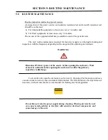
Page 67: ...spection with the frequency depending on the usage and the operating environment WARNING Disconnect Primary power at the source before opening the enclosure Wait at least two minutes before opening the enclosure to allow the primary capacitors to discharge To clean the unit open the enclosure see Section 9 1 Opening The Enclosure and use a vacuum cleaner to remove any accumulated dirt and dust The...

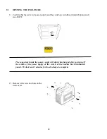
Page 68: ...rd distribution panel are all OFF The capacitors inside the power supply will slowly discharged after you turn off the switch of the power supply or the switch at the breaker box distribution panel Wait at least 5 minutes for the discharge to complete 2 Remove all screws and nuts on the side covers ...

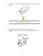
Page 69: ... turning them approximately two turns CCW NOTE DO NOT remove the screws completely 4 Pull the front panel slightly forward and pull the rear panel slightly backward The interlocking hooks of the side case covers can now be disengaged from the front and rear panels ...

Page 70: ...70 5 Remove the side covers 6 Remove protection cover sheet by removing the plastic tabs NOTE When you re assemble the parts conduct the above process backwards ...

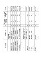
Page 71: ... CON1 CT2 D1 D2 D4 D5 FAN1 FCH1 HCT1 HF UNIT1 QTY 1 1 1 1 1 1 1 1 1 1 1 1 1 1 TYPE RATING ECQE12104KF DC1250V 0 1M FGSM 167 400V206J SL DC400V 20uF F3A040602 200A CC Or F3A040600 N MS3102A20 27S with wiring assy F2A503001 CT 1 40 DFA100BA160R DBA200UA60R DBA200UA60R DBA200UA60R 109E5724H507 DC 24V 16 8W with wiring assy F3A285101 AC DC FCH HC TN200V4B15M 200A 4V HF UNIT assy with gap NO RESISTORS ...

Page 72: ...CB1 PCB2 PCB3 PCB4 PCB5 PCB6 PCB7 QTY 1 1 1 1 1 1 1 TYPE RATING WK 5477 U03 MAIN PCB or WK 5477 WK 5482 U02 LINK PCB or WK 5482 WK 5548 U13 DDC PCB or WK 5548 WK 4819 U12 DETECT PCB or WK 4819 U01 WK 5551 U03 CONNECT PCB or WK 5551 WK 5549 U10 200A CTRL PCB or WK 5549 U07 WK 5550 U03 FILTER PCB or WK 5550 DESCRIPTION Printed Circuit Board Printed Circuit Board Printed Circuit Board Printed Circuit...

Page 73: ...PE RATING WK 5479 U07 U01 GATE PCB KIT with IGBT Spring Clip Silicon Rubber Sheet WK 5527 U13 RoHS ACDC PANEL PCB or WK 5527 U21 WK 5528 U03 ENCODER PCB or WK 5528 WK 5615 U02 DIODE SNUBBER PCB or WK 5615 WK 5569 U03 GATE INPOSE PCB or WK 5569 WK 5570 U03 IGBT SNUBBER PCB or WK 5570 WK 5499 U06 FILTER PCB or WK 5499 WK 4917 U15 AC INPUT FILTER PCB or WK 4917 U12 DESCRIPTION Printed Circuit Board P...

Page 74: ... 1 1 2 TYPE RATING GCA200EA60R with WK 3367 U08 ERG3SJ220H 3W 22Ω JG23V101J 68W 100Ω Parallel MHS20A221KI 20W 220Ω MHS20A101KI 20W 100Ω DCP 53SR50C 480V 3P 480V SDKGA4 A 1 A SLIDE SWITCH 5505NBR1 5 DC24V 11VA 10W with Gas Inlet and PC4 02 F3A063501 200A MAIN TR or F3A063500 PTP 46F S1 Assembly PTP 46F S1 Assembly E00D0001100 E0D005501 E0D005411 DESCRIPTION Transistor Resistor on HF Unit1 Resistor ...

Page 75: ...FERENCE n a n a n a n a n a n a n a n a n a n a QTY 1 1 1 1 1 2 2 1 1 1 TYPE RATING E0C346000 JDA173200 E0C303200 with E2B058600 EBA514400 E1B537600 with Dustcover Sheet N4A084600 N4A009300 N1B029700 Safety Instructions N1B029800 Two Warnings N4A040100 DESCRIPTION Front Control Cover Rear Control Cover Protection Cover Encoder Cover PCB Cover Name Label Side Label Warning Label 1 Warning Label 2 O...

Page 76: ...AGRAM REFERENCE n a n a n a n a n a n a n a n a n a n a n a n a n a n a QTY 1 1 1 2 2 1 1 2 1 4 1 1 set 1 1 TYPE RATING N4A040700 N4A148700 E5A925600 with PC4 02 TRAK BE35 70S SOOW AWG12X4C EBA045800 E1B869900 E1B870000 E1B850100 J5B017400 J3C356500 two piece set 2621603 3021104 DESCRIPTION GAS Input Label Switch Label GAS Outlet C Ring Output Terminal female Input Cable Input Cable Clamp Heatsink...

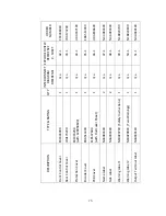
Page 77: ...ERENCE n a n a n a n a n a n a n a n a n a n a n a n a QTY 1 2 3 1 1 1 1 3 1 1 1 2 TYPE RATING N00B0177500 EDA227700 EBA424900 M4 M5 ECA879500 ECA879600 ECA887200 ECA887300 ECA321000 ECA901400 ECA904200 EDA022400 E1B872000 Divisible into two DESCRIPTION Control Cover Sheet Mylar Silicone Rubber Sheet Post1 M5 For S1 D L Bus Bar1 D L Bus Bar2 T D Bus Bar1 T D Bus Bar2 S1 Bus Bar Q13 Output Bus Bar ...

Page 78: ... a n a n a n a n a n a n a n a n a n a n a n a n a QTY 1 1 1 1 1 1 4 1 1 1 1 2 1 TYPE RATING E00A0616800 J00A0707500 E1B859500 EDA174000 E1B935200 E1B935600 74 NATURAL 0250468000 with String Clip ECA900600 T0425B Nylon Hose L 0 5m N00A0711900 TRAK SK50 E5A937000 DESCRIPTION C2 Board C2 Chassis PCB1 Insulated Sheet PCB3 Insulated Sheet Dust Cover Sheet Front Dust Cover Sheet Rear Clip CON1 Dust Cov...

Page 79: ...79 PAGE LEFT INTENTIONALLY BLANK ...

Page 80: ...80 10 1 INTERCONNECT DIAGRAM 200AP ...

Page 81: ...81 ...

Page 82: ...82 10 2 EXPLODED VIEW 200AP ...

Page 83: ...83 ...

Page 84: ...84 PAGE LEFT INTENTIONALLY BLANK ...

Page 85: ...PEAT Additional Slope function for current control while in the Weld Current sequence activated through the remote ON OFF device For a detailed description of the Slope Slope w Repeat functions see your owner s manual under the Slope Mode Sequence section NOTE All Slope functions operate with a Remote ON OFF switch device only SPOT A timed HF TIG operation using a remote ON OFF device Parameter Fu...

Page 86: ...quence Graph Pushing the knob inward displays the actual welding voltage The welding voltage is for reference purposes only and is not a machine adjustable value Detailed description of each parameter can be found in the Owner s Manual SANARG 200AP SETTINGS The settings shown below should be used as guidelines for a first set up The welder should adjust these setting to achieve optimal weld perfor...

Page 87: ...ditional Slope function for current control while in the Weld Current sequence activated through the remote ON OFF device For a detailed description of the Slope Slope w Repeat functions see your owner s manual under the Slope Mode Sequence section NOTE All Slope functions operate with a Remote ON OFF switch device only SPOT A timed HF TIG operation using a remote ON OFF device Parameter Functions...

Page 88: ...ence Graph Pushing the knob inward displays the actual welding voltage The welding voltage is for reference purposes only and is not a machine adjustable value Detailed description of each parameter can be found in the Owner s Manual SANARG 200AP SETTINGS The settings shown below should be used as guidelines for a first set up The welder should adjust these setting to achieve optimal weld performa...

Page 89: ...PAGE LEFT INTENTIONALLY BLANK ...

Page 90: ...SanRex SANREX CORPORATION USA 50 Seaview Blvd Port Washington NY 11050 SANSHA ELECTRIC MFG CO LTD Japan 301056 Nishi Awaji Higashiyodogawa Osaka Japan 533 0031 ...

Reviews: