background image


SAS-to-SATA II RAID Subsystem 

23


Installation and Configuration Manual                                                                                                                                


1.5.4.2   Hot-Swap Disk Drive Support


The RAID subsystem has built-in protection circuit to support the replacement of SATA 
II hard disk drives without having to shut down or reboot the system. The removable 
hard drive tray can deliver “hot swappable” fault-tolerant RAID solution at a price much 
less than the cost of conventional SCSI hard disk RAID subsystems. This feature is 
provided in the RAID subsystem for advance fault tolerant RAID protection and “online” 
drive replacement. 
 

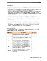
1.5.4.3   Hot-Swap Disk Rebuild 


The Hot-Swap feature can be used to rebuild Raid Sets with data redundancy such as RAID 
level 1, 0+1, 3, 5 and 6. If a hot spare is not available, the failed disk drive must be 
replaced with a new disk drive so that the data on the failed drive can be rebuilt. If a hot 
spare is available, the rebuild starts automatically when a drive fails. The RAID subsystem 
automatically and transparently rebuilds failed drives in the background with user-
definable rebuild rates. The RAID subsystem will automatically continue the rebuild 
process if the subsystem is shut down or powered off abnormally during a reconstruction 
process.  


Summary of Contents for Mobileraid MR8X

Page 1: ...DETAILED USER S MANUAL v1 0 MOBILERAID MR8X...

Page 2: ...3 1 InstantAvailability Background Initialization 21 1 5 3 2 Array Roaming 21 1 5 3 3 Online Capacity Expansion 21 1 5 3 4 Online RAID Level and Stripe Size Migration 22 1 5 4 High Availability 22 1...

Page 3: ...Physical Drive 57 4 4 1 Create Pass Through Disk 57 4 4 2 Modify Pass Through Disk 58 4 4 3 Delete Pass Through Disk 59 4 4 4 Identify Selected Drive 59 4 5 System Controls 60 4 5 1 System Configurati...

Page 4: ...gh with this manual Copyright No part of this publication may be reproduced stored in a retrieval system or transmitted in any form or by any means electronic mechanical photocopying recording or othe...

Page 5: ...terference to radio communications However there is not guarantee that interference will not occur in a particular installation If this equipment does cause interference to radio or television equipme...

Page 6: ...lowed ambient temperature Before plugging in any power cords cables and connectors make sure that the power switches are turned off Disconnect first any power connection if the power supply module is...

Page 7: ...and Configuration Manual Unpacking the Subsystem The package contains the following items RAID subsystem unit One power cord One RJ 45 Ethernet cable One external serial cable Two external SAS cables...

Page 8: ...dular design allows hot swapping of hard drives without interrupting the subsystem s operation Highest Density Available Small Desktop Tower with 8 bay carriers Support Over 2TB Extraordinary performa...

Page 9: ...nection Built in serial port interface for remote event notification Dual host channels support clustering technology Tagged command queuing for 256 commands allows for overlapping data streams Transp...

Page 10: ...terface SATA II 3Gb s Data Transfer Rate Up to 300MB Sec per channel Hot Swap Drive Trays Eight 8 1 inch trays Power Supply 300W w PFC Cooling Fans 2 Battery Backup Option MAID Support Yes R Link Supp...

Page 11: ...SAS to SATA II RAID Subsystem 11 Installation and Configuration Manual 1 2 Identifying Parts of the RAID Subsystem The illustrations below identify the various parts of the subsystem 1 2 1 Front View...

Page 12: ...configure the subsystem Select button This is used to enter the option you have selected Exit button EXIT Press this button to return to the previous menu Environment Status Parts Function Disk Fault...

Page 13: ...when the hard drive is being accessed HDD Fault LED Red LED indicates no hard drive or hard drive has failed No LED light means HDD is detected good Lock Indicator Every Drive Tray is lockable and is...

Page 14: ...system s equipped with one 10 100 Ethernet RJ45 LAN port You use a web browser to manage the RAID subsystem through Ethernet for remote configuration and monitoring SAS Host A and SAS Host B The subsy...

Page 15: ...s or as large as several megabytes These stripes are then interleaved in a rotating sequence so that the combined space is composed alternately of stripes from each drive The specific type of operatin...

Page 16: ...though striping is not used within a single mirrored drive pair multiple RAID 1 arrays can be striped together to create a single large array consisting of pairs of mirrored drives All writes must go...

Page 17: ...3 arrays in order to avoid performance degradation with short records RAID 5 arrays with small stripes can yield similar performance to RAID 3 arrays Under RAID 5 parity information is distributed acr...

Page 18: ...vel 5 which allows for additional fault tolerance by using a second independent distributed parity scheme two dimensional parity Data is striped on a block level across a set of drives just like in RA...

Page 19: ...esults in a huge increase in performance over parallel SCSI No bit skewing and is self clocking Transfer rates up to 3 0 Gb s per link Full duplex which results in a total of 6 0 Gb s per link Link ag...

Page 20: ...are grouped together in a Raid Set then the capacity of the smallest disk will become the effective capacity of all the disks in the Raid Set 1 5 2 Volume Set A Volume Set is seen by the host system...

Page 21: ...stores configuration information both in NVRAM and on the disk drives This protects the configuration settings in the case of a disk drive or controller failure Array roaming allows the administrator...

Page 22: ...sk you have the option of adding this disk to your existing RAID logical drive and migrating from RAID level 1 to 5 The result would be parity fault tolerance and double the available capacity without...

Page 23: ...erant RAID protection and online drive replacement 1 5 4 3 Hot Swap Disk Rebuild The Hot Swap feature can be used to rebuild Raid Sets with data redundancy such as RAID level 1 0 1 3 5 and 6 If a hot...

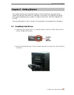
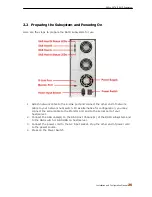
Page 24: ...system supports hot swapping allowing you to install or replace a hard drive while the subsystem is running This also discusses on how to power on the subsystem in preparation for operation 2 1 Instal...

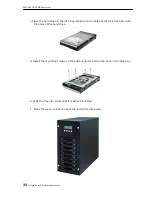
Page 25: ...the disk tray Make sure the holes of the disk tray align with the holes of the hard drive d Install the mounting screws on the bottom part to secure the drive in the disk tray e Slide the tray into a...

Page 26: ...er end of network cable to your network hub switch Or as alternative for configuration you may connect the serial cable to the Monitor port and to the serial port of your host server 2 Connect the SAS...

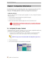
Page 27: ...rial port Front panel touch control keypad Web browser based Remote RAID management via the R Link ethernet port IMPORTANT The subsystem allows you to access the utility using only one method at a tim...

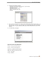
Page 28: ...SAS to SATA II RAID Subsystem Installation and Configuration Manual 28 4 The default setting of the monitor port is 115200 baud rate 8 data bit non parity 1 stop bit and no flow control...

Page 29: ...SAS to SATA II RAID Subsystem 29 Installation and Configuration Manual 5 Click disconnect button 6 Open the File menu and then open Properties 7 Open the Settings Tab...

Page 30: ...e VT100 is ready to use After you have finished the VT100 Terminal setup you may press the X key in your Terminal to link the RAID subsystem and Terminal together Press X key to display the disk array...

Page 31: ...eature Once the password has been set the user can only monitor and configure the RAID subsystem by providing the correct password The password is used to protect the RAID subsystem from unauthorized...

Page 32: ...e a RAID configuration which consists of all physical disks installed Raid Set Functions Create a customized Raid Set Volume Set Functions Create a customized Volume Set Physical Drive Functions View...

Page 33: ...nus The LCD screen displays up to two lines at a time of menu items or other information The RAID subsystem s factory default password is set to 00000000 Function Key Definitions The four function key...

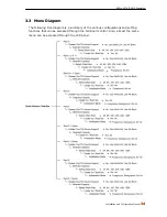
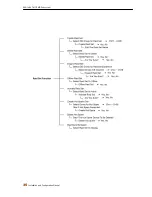
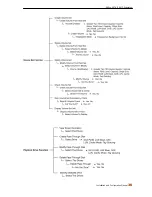
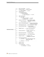
Page 34: ...Configuration Manual 34 3 3 Menu Diagram The following tree diagram is a summary of the various configurations and setting functions that can be accessed through the terminal monitor Also almost the s...

Page 35: ...SAS to SATA II RAID Subsystem 35 Installation and Configuration Manual...

Page 36: ...SAS to SATA II RAID Subsystem Installation and Configuration Manual 36...

Page 37: ...SAS to SATA II RAID Subsystem 37 Installation and Configuration Manual...

Page 38: ...SAS to SATA II RAID Subsystem Installation and Configuration Manual 38...

Page 39: ...function To configure the RAID subsystem on a remote machine you need to know its IP Address Launch your web browser by entering http IP Address in the remote web browser IMPORTANT The Ethernet defau...

Page 40: ...modified during setup Raid Set Functions Create customized Raid Sets Volume Set Functions Create customized Volume Sets and allow modification of parameters of existing Volume Sets parameter Physical...

Page 41: ...er Two TB Volume Support No Volume Set capacity is set to maximum 2TB 64bit LBA Use this option for UNIX Linux and Windows Server 2003 SP1 or later versions The maximum Volume Set size is up to 512TB...

Page 42: ...time or to delete existing Raid Set and reconfigure a Raid Set 4 2 1 Create Raid Set To create a Raid Set click on the Create Raid Set link A Select The IDE Drives For RAID Set screen is displayed sho...

Page 43: ...k on the Submit button to proceed with deletion 4 2 3 Expand Raid Set Use this option to expand a Raid Set when one or more disk drives is are added to the subsystem This function is active when at le...

Page 44: ...rebuild operation will occur after the Raid Set expansion is completed Migration occurs when a disk is added to a Raid Set Migrating status is displayed in the Raid Set status area of the Raid Set inf...

Page 45: ...ction After completing the function the HDD state will change to Offlined Mode To offline a Raid Set click on the Offline Raid Set link A Select The RAID SET To Offline screen is displayed showing all...

Page 46: ...ere is no failed disk drive When does Incomplete Raid Set State Happens If the RAID subsystem is powered off and one disk drive is removed or has failed in power off state and when the RAID subsystem...

Page 47: ...Set click on the Activate Raid Set link A Select The Raid Set To Activate screen is displayed showing all existing Raid Sets in the subsystem Select the Raid Set with Incomplete state which you want t...

Page 48: ...all unused non Raid Set member disk drives in the subsystem appear Select the target disk drive by clicking on the appropriate check box Tick on the Confirm The Operation and click on the Submit butt...

Page 49: ...SAS to SATA II RAID Subsystem 49 Installation and Configuration Manual 4 2 8 Rescue Raid Set If you need to rescue a missing Raid Set please contact your vendor s support engineer for assistance...

Page 50: ...t on the Raid Set will have its data spread evenly across all the disks in the Raid Set 4 3 1 Create Volume Set The following are the Volume Set features 1 Volume sets of different RAID levels may coe...

Page 51: ...Two TB Volume Support will be automatically provided in the screen as shown in the example above There are three options to select No 64bit LBA and 4K Block No Volume Set size is set to maximum 2TB li...

Page 52: ...D controller acknowledges data has been received when it reaches the controller s cache memory This provides better performance but requires a battery module support for the cache memory or a UPS to c...

Page 53: ...check the Confirm The Operation option and then click on the Submit button to show all Volume Sets in the selected Raid Set Tick on a Volume Set and check the Confirm The Operation option Click on the...

Page 54: ...y can be used to enlarge the Volume Set size or create another Volume Set Use the Modify Volume Set function to expand the Volume Set capacity Select the Volume Set and move the cursor to the Volume S...

Page 55: ...ports this function To perform Check Volume Set function 1 Click on the Check Volume Set link 2 Tick from the list the Volume Set you want to check Select the Check Volume Set options Check Volume Set...

Page 56: ...SAS to SATA II RAID Subsystem Installation and Configuration Manual 56 4 3 6 Stop Check Volume Set Use this option to stop Volume Set consistency checking...

Page 57: ...Set A Pass Through disk is a separate and individual Raid Set The disk is available to the host as an individual disk It is typically used on a system where the operating system is on a disk not contr...

Page 58: ...Base LUN on an existing Pass Through Disk To modify the Pass Through drive attribute from the Pass Through drive pool click on the Modify Pass Through link The Select The Pass Through Disk For Modifi...

Page 59: ...4 4 4 Identify Selected Drive Use this option to physically locate a selected drive to prevent removing the wrong drive When a disk drive is selected using the Identify Drive function the Status LED...

Page 60: ...k Priority indicates how much time and system resource the RAID controller devotes to a background task such as a rebuild operation The RAID subsystem allows user to choose the background task priorit...

Page 61: ...correctly Volume Data Read Ahead This option allows the users to set the Volume Data Read Ahead function Options are Normal Aggressive Conservative and Disabled Stagger Power On Control This option a...

Page 62: ...pacity varies slightly For example one drive might be 121 1 GB and the other 120 4 GB This drive truncation mode makes the 121 1 GB and 120 4 GB drives same capacity as 120 GB so that one could replac...

Page 63: ...herNet Configuration screen will be shown Set the desired configuration Once done tick on the Confirm The Operation and click the Submit button to save the settings 4 5 2 1 DHCP Host Name Support If D...

Page 64: ...By Mail Config link under the System Controls main menu The RAID subsystem Event Notification configuration screen will be shown Set up the desired function and option When an abnormal condition occu...

Page 65: ...hown Select the desired function and set the preferred option SNMP Trap Configurations Type in the SNMP Trap IP Address box the IP address of the host system where SNMP traps will be sent The SNMP Por...

Page 66: ...otocol It is an Internet protocol used to synchronize the clocks of computers to some time reference Type the NTP Server IP Address to enable the RAID subsystem to synchronize with it To set the NTP f...

Page 67: ...ation screen appears The System Events Information screen will show Time Device Event type Elapse Time and Errors The RAID system does not have built in real time clock When the RAID manager GUI is op...

Page 68: ...t events move the cursor bar to the main menu and click on the Generate Test Events Link Tick on the Confirm The Operation and click on the Submit button Then click on the View Events Mute Beeper to v...

Page 69: ...The RAID controller will check the password only when entering the Main Menu from the initial screen The RAID subsystem will automatically go back to the initial screen when it does not receive any co...

Page 70: ...ew the RAID subsystem s existing Raid Set s Volume Set s and physical disk s configuration and information Select the RaidSet Hierarchy link from the Information menu to display the Raid Set Hierarchy...

Page 71: ...ror count and SMART information The SMART information shows two numbers one on the left attribute value and one on the right enclosed in parentheses threshold The higher the attribute value compared t...

Page 72: ...ew the RAID subsystem s controller information click the System Information link from the Information menu The Raid Subsystem Information screen appears The controller name firmware version serial num...

Page 73: ...s Polling is disabled in System Configuration The Hardware Monitor Information provides the temperature and voltage levels of the RAID subsystem All items are also unchangeable When the threshold valu...

Page 74: ...onfiguration method Each configuration method requires a different level of user input The general flow of operations for Raid Set and Volume Set configuration is Step Action 1 Designate hot spare dis...

Page 75: ...rsion README TXT It contains the history information of the firmware change Read this file first before upgrading the firmware These files must be extracted from the compressed file and copied to one...

Page 76: ...t ROM firmware that needs to be upgraded upgrade first the boot ROM firmware Then repeat the process steps 1 to 9 to upgrade the firmware code after which a RAID controller restart will be necessary 1...

Page 77: ...nstallation and Configuration Manual 5 Click Browse Look in the location where the firmware file was saved Select the firmware file name xxxxxxxx BIN and click Open 6 Click Send to send the firmware b...

Page 78: ...he firmware downloading is completed the confirmation screen appears Select Yesto start programming the flash ROM 8 When the Flash programming starts a message will show Start Updating Firmware Please...

Page 79: ...stem 79 Installation and Configuration Manual 10 After the firmware upgrade is complete a message will show Firmware Has Been Updated Successfully Restarting the RAID controller is required for the ne...

Page 80: ...rmware code after which a RAID controller restart will be necessary 1 To upgrade the RAID subsystem firmware click the Upgrade Firmware link under System Controls menu The Upgrade The Raid System Firm...

Page 81: ...stem 81 Installation and Configuration Manual 5 After the firmware upgrade is complete a message will show Firmware Has Been Updated Successfully Restarting the RAID controller is required for the new...

Reviews: