


Blower does not run with fan switch in either position.
Compressor runs briefly but cycles ON & OFF.
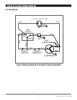
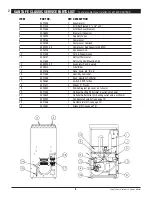
1. Loose connection in blower circuit (see Fig. 2).
2. Obstruction prevents impeller rotation.
3. Defective blower.
4. Blower switch defective.
Evaporator coil frosted continuously, low dehumidifying
capacity.
1. Defrost thermostat loose or defective (Sec. 5.8).
2. Low refrigerant charge.
3. Dirty air filter or air flow restricted.
5.4 Refrigerant Charging
If the refrigerant charge is lost due to service or a leak, a new
charge must be accurately weighed in. If any of the old charge is
left in the system, it must be removed before weighing in the new
charge. Refer to the unit nameplate for the correct charge weight
and refrigerant type.
5.5 Blower Replacement
The centrifugal blower has a PSC motor and internal thermal
overload protection. If defective, the complete assembly must be
replaced.
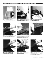
1. Unplug the power cord.
2. If an outlet duct is connected to the unit, remove it.
3. Remove the cabinet side.
4. Remove the 4 screws holding the electrical box located next to
the blower.
5. Disconnect the blower leads. Black from the blower switch,
and white from the run capacitor.
6. Unbolt the blower capacitor from the blower motor (required
for removal clearance).
7. Remove the nuts & bolts holding the blower outlet flange to
the cabinet end and remove the blower.
8. Reassembling with the new blower is the above procedure
reversed.
5.6 Compressor/Capacitor Replacement
This compressor is equipped with a two terminal external overload
run capacitor, but no start capacitor or relay (see Fig. 2).
CAUTION!
ELECTRIC SHOCK HAZARD: Electrical power must be present
to perform some tests; these tests should be performed by a
qualified service person.
5.6A Checking Compressor Motor Circuits
Perform the following tests if the blower runs but the
compressor does not with the blower switch OFF and the
humidity control ON.
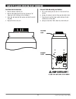
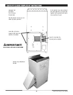
1. Unplug the unit, remove the cabinet side (with two screws
in center) and the electrical connection cover on the
compressor top.
2. Plug in the unit and turn the humidity control to ON. Check
for 110 volts from compressor terminal R to overload
terminal 3 using an AC voltmeter. If voltage is present, go
to step 3. If no voltage, the high pressure control or relay
are open or there is a loose connection in the compressor
circuit. Test each component for continuity; see the
appropriate section if a defect is suspected.
3. Unplug the unit, then disconnect the red and yellow wires
from compressor terminals R & S. Using an ohmmeter,
check continuity between the points listed below.
4. Compressor terminals C and S: No continuity indicates an
open start winding. The compressor must be replaced.
Normal start winding resistance 3 to 7 ohms.
5. Compressor terminals C and R: No continuity indicates
an open run winding. The compressor must be replaced.
Normal run winding resistance is .5 to 2 ohms.
6. Compressor terminal C and overload terminal 1: No
continuity indicates a defective overload lead.
7. Overload terminals 1 and 3: If there is no continuity, the
overload may be tripped. Wait 10 minutes and try again.
If there is still no continuity, it is defective and must be
replaced.
8. Compressor terminal C and compressor case: Continuity
indicates a grounded motor. The compressor must be
replaced.
9. Disconnect the yellow wires from the capacitor. Set the
ohmmeter to the Rx1 scale. The capacitor is shorted and
must be replaced if continuity exists across its terminals.
If there is no needle movement with the meter set on
the Rx100000 scale, the capacitor is open and must be
replaced.
10. Reconnect the wires to the compressor and capacitor. Plug
in and turn on the unit. If the compressor fails to start,
replace the run capacitor.
11. If the unit doesn’t start, adding a hard-start kit (relay
& capacitor) will provide greater starting torque. If this
doesn’t work, the compressor has an internal mechanical
defect and must be replaced.
5.6B Replacing a Burned Out Compressor
The refrigerant and oil mixture in a compressor is chemically
very stable under normal operating conditions. However,
when an electrical short occurs in the compressor motor,
the resulting high temperature arc causes a portion of the
refrigerant oil mixture to break down into carbonaceous sludge,
a very corrosive acid and water. These contaminants must be
carefully removed otherwise even small residues will attack
replacement compressor motors and cause failures.
The following procedure is effective only if the system is
monitored after replacing the compressor to insure that the
clean up was complete.
1. This procedure assumes that the previously listed
compressor motor circuit tests revealed a shorted or open
SANTA FE CLASSIC INSTALLER'S AND OWNER'S MANUAL
5
Santa Fe Classic Installer’s & Owner’s Manual


