


winding. If so, cautiously smell the frigerant from the
compressor service port for the acid odor of a burn out.
2. Remove and properly dispose of the system charge. DO
NOT vent the refrigerant indoors or allow it to contact your
eyes or skin.
3. Remove the burned out compressor. Use rubber gloves if
there is any possibility of contacting the oil or sludge.
4. To facilitate subsequent steps, determine the type of burn
out that occurred. If the discharge line shows no evidence
of sludge and the suction line is also clean or perhaps
has some light carbon deposits, the burn out occurred
while the compressor was not rotating. Contaminants are
therefore largely confined to the compressor housing. A
single installation of liquid and suction line filter/driers will
probably clean up the system.
If sludge is evident in the discharge line, it will likely be found
in the suction line. This indicates the compressor burned out
while running. Sludge and acid has been pumped throughout
the system. Several changes of the liquid and suction filter/
driers will probably be necessary to cleanse the system.
5. Correct the system fault that caused the burn out. Consult
the factory for advice.
6. Install the replacement compressor with a new capacitor
and an oversized liquid line filter. In a running burn
out, install an oversized suction line filter/drier between
the accumulator and compressor. Thoroughly flush the
accumulator with refrigerant to remove all trapped sludge
and to prevent the oil hole from becoming plugged. A
standing burn out does not require a suction line filter/drier.
7. Evacuate the system with a good vacuum pump and
accurate vacuum gauge. Leave the pump on the system for
at least an hour.
An alternate method of removing moisture and non-
condensibles from the system requires evacuation to 29" Hg
vacuum. Then break the vacuum with 35 to 50 PSIG refrigerant
vapor charge. Leave the vapor charge in the system from at
least 5 minutes before removing it. Repeat the vapor charge/
wait/remove sequence twice more and then charge the system
with the quantity and refrigerant listed on the nameplate.
8. Operate the system for a short period of time, monitoring
the suction pressure to determine that the suction filter
is not becoming plugged. Replace the suction filter/drier
if pressure drop occurs. If a severe running burn out has
occurred, several filters/driers may have to be replaced to
remove all of the acid and moisture.
NOTE: NEVER
use the compressor to evacuate the system or any
part of it.
5.6C Replacing a Compressor - Nonburn Out
Remove the refrigerant from the system. Replace the compressor
and liquid line filter/drier. Charge the system to 50 PSIG and
check for leaks. Remove the charge and weigh in the refrigerant
quantity listed on the nameplate. Operate the system to verify
performance.
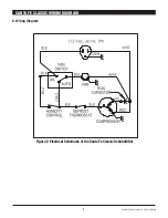
5.7 Humidity Control
The humidity control is an adjustable switch that closes when the
relative humidity of the air in which it is located rises to the dial
set point. It opens when the RH drops 4 to 6% below the set point.
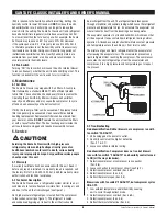
5.8 Defrost Thermostat
The defrost thermostat is attached to the refrigerant
suction tube between the accumulator and compressor. It will
automatically shut the compressor off if the low side
refrigerant temperature drops due to excessive frost formation
on the evaporator coil. The blower will continue to run, causing
air to flow through the evaporator coil and melt the ice. When
the ice has melted, the evaporator temperature will rise and the
thermostat will restart the compressor.
SANTA FE CLASSIC INSTALLER'S AND OWNER'S MANUAL
6
Santa Fe Classic Installer’s & Owner’s Manual


