15
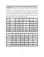
Remark:
1. Prior to connecting the power distribution system to the UPS, make sure the
rated triploid-pole over-current breaker is installed to break off all the input lines
and the N line breaker can be congured individually.
2. When single-phase current exceeds 100A, switches of protective atmosphere
should be equipped with arc control devices,It should be D-curve air switch with
UL certication according to the customer requirement;
3. Battery positive/negative/N wire size: indicates UPS and battery bank wire size;
red wire signies the positive polarity and black wire the negative, while blue wire
the neutral.
4. There should be the same length of the battery wires (positive, negative and N)
of being no more than 40m.
3.5 Parallel UPS installation
1. Redundancy introduction
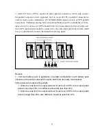
N+X is currently the most reliable power supply structure, in which N indicates the
minimum UPS number required for the total load and X is the redundant UPS number,
namely, the malfunctioning UPS number that the system can simultaneously bear. The
larger X is, the higher reliability of system will be. For instance, if the total loads of a
customer register 55kVA, we can use Castle 20KS for N+X design. With N taking up 3,
X can be selected in accordance with reliability degree or cost requirement. Supposing
customer selects X=2 and equalized UPS power supply is 11kVA for each unit, when one
set of UPS breaks down with malfunction, the remaining four sets will provide power
with almost 14kVA equalized current; if two sets of UPS fail, the remaining three sets of
UPS are supposed to provide power supply with almost 18kVA equalized current. The
maximum allowance of this system is for two sets of UPS going down at the same time,
the chances of which are much smaller than those of one UPS malfunction. Therefore, the
reliability degree can be largely enhanced, making it an optimal mode for application in
locations where high degree of reliability is always a focus.


