16
2.3 Part names and functions
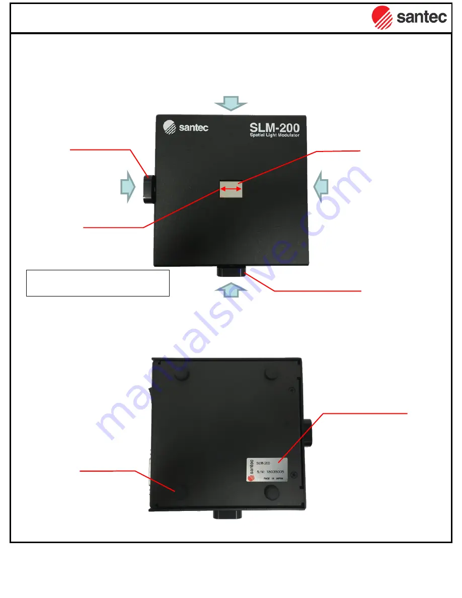
All-in-one model
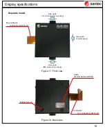
Figure 11: Front view.
Figure 12: Back view.
Display specifications
Rubber legs x4
Label
(Model name and S/N)
Side view1
(Control panel)
Side view2
(M6 screw for mounting)
Side view3
(1/4 inch screw for mounting)
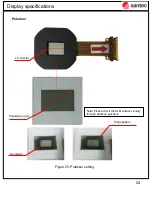
display
LCOS panel
M6 screw for mounting
¼ inch screw
for mounting
LC director
Note: Input linear polarized light
shall be parallel to the LC director.
LCOS display
Side view4
(M2.6 screw)
Summary of Contents for LCOS-SLM
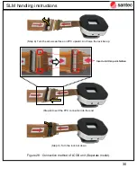
Page 6: ...6 Introduction Figure 2 LCOS unit handling...
Page 12: ...12 Display specifications Figure 6 Dimensions All in one model Unit mm...
Page 13: ...13 Display specifications Figure 7 Dimensions Separate model Unit mm...
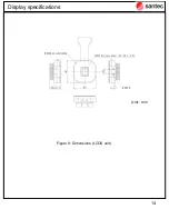
Page 14: ...14 Display specifications Figure 8 Dimensions LCOS unit Unit mm...
Page 23: ...23 Figure 24 Side view Display specifications 6 M2 6 screw hole for mounting...
Page 36: ...36 2 Please select Browse my computer for driver software Software package...
Page 37: ...37 3 Select adequate OS folder on attached CD contents Software package...
Page 38: ...38 4 Installation of USB driver Software package...
Page 51: ...51 4 2 2 8 Set CSV pattern The preview of specified display data is displayed Software package...
Page 70: ...70 4 3 3 Effective area of BMP image Software package...

