background image


17

3.4 HDD Information and channel selection 


3.4.1


HDD information 


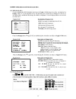
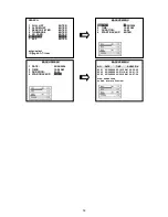
You  can  display  the  HDD  information  as  shown  on 

Figure 3.3 A

  below  at  any  time  by  pressing  the 

Display

  button 

.  In  the  playback  mode,  the  recorded  video  information  is  displayed.  In  the  live  or 

recording mode, the Manual Recording information is displayed. The unit displays status on a monitor 
as shown next. 


Figure 3.4 A.   


Description of Figure 3.4 A 


(20G): 

The capacity of installed hard disk, 20 GB. 


(HDD): 

Hard disk Compartment.


(

): 

Recording; 

(

): 

No


recording. 

(

): 

Playback; 

( ): 

No


Playback. 

(SD CARD): 

SD CARD Compartment. 


Press the 

Display 

button 

  again; the unit will display the information as shown in 

Figure 3.3 B

 below. 


Figure 3.4 B.                                                            Description of Figure 3.4 B   


(30 F/S): 

Record speed setting: 30 frames/sec.


(5h18m): 

Total 5 hours and 18 minutes recording time available. 

(1h10m): 

Total 1 hours and 10 minutes remaining time available.


(REC MODE): 

STOP; MANUAL.


(STATUS): 

Indicates the device status.


                                    PLAY

: The device is in the playback mode.   

LIVE

: The device is in the live display mode. 

MANU

:

 The device is in the search mode.


(SCHEDULE): 

NORMAL, and 1~8.


Press the 

Display 

button 

  again; the unit will display the information as shown in 

Figure 3.3 C 

below. 


Figure 3.4 C.                                                            Description of Figure 3.4 C   

  (DHCP): 

Enables the DHCP communication function.


(

192.168.1.143

): 

Every DVR has to own an IP address to 

be identified on the network.


(RX     

29  KB/S

): 

Receives  the  data  from  the  network 

every per second.


(TX     

100  KB/S

): 

Transmits  the  data  to  network  every 

second.


3.4.2 Channel Selection 


The 

, and CH1/ CH2/ CH3/ 

/CH9 buttons are used to select video modes and 

video channels. The following table shows the functions under different modes. 


Mode 

Key 

Result Display   

Live / Record / Playback 


 

  then loop back 


 


then loop back


 


then loop back


CH1/ CH2/ CH3/ 

/CH9 

  ( Single channel ) 


ETHERNET    DHCP 
1 9 2 . 1 6 8 . 1 . 1 4 3 
RX                  29      KB/S


TX                  100    KB/S 


REC RATE:    30 F/S 

REC TIME:    5h18m 

REMAIN:   

1h10m 

REC MODE:    STOP 


STATUS:  LIVE 

SCHEDULE:  NORMAL 

Summary of Contents for SDVR-9/X-S

Page 1: ...Version 1 0rn 2009 USER MANUAL Digital Video Recorder Model SDVR 9 X S...

Page 2: ...units are installed to get enough air flow for safe operation The maximum temperature for rack mounted units is 40 C Avoid uneven loading or mechanical instability when rack mounting units Check produ...

Page 3: ...shock hazard CAUTION Danger of explosion if the Lithium battery RTC Battery is incorrectly replaced Danger of explosion if battery is incorrectly replaced Replace only with the same or equivalent type...

Page 4: ...3 Alarm Recording 22 4 1 4 Externally triggered Recording 23 4 1 5 Possible Recording Time 24 4 2 Playback Operations 26 4 2 1 Fast Forward Reverse 26 4 2 2 Slow Forward Reverse 26 4 2 3 Playback Pic...

Page 5: ...ding on 9 channel DVR 48 5 6 3 2 How to Set Up Advanced Motion Detection Recording on 9 channel DVR 48 5 6 4 COVER CAMERA 49 5 6 5 OPERATION LOCK 49 5 6 6 COMMUNICATION 50 5 6 7 DISK SETUP 52 5 6 8 SC...

Page 6: ...a can be assigned to any channel location under a multi screen display mode in both live viewing and playback mode 9 way 8 way 6 way 4 way 3 way 2 way Refresh rate up to 60 field sec for 720X240 NTSC...

Page 7: ...each channel Power on interruption recovery Operation status record log Multi lock out functions front key lock RS 232 lock play back lock and recording lock Three audio quality levels 8 22 44 kHz sa...

Page 8: ...the HDD status of the Mobile Rack The orange light indicates the HDD is storing or retrieving data 5 Jog Dial This dial can act in both a forward and a backward direction as well as step by step Turn...

Page 9: ...play modes press thrice successively to get three multi channel modes on the main monitor the first two times in a 3 way vision and the last in a 4 way mode 13 Up buttons Press to move the focus in th...

Page 10: ...l button All channel buttons from 1 to 9 are sited here Press each to display its channel in the live and play modes 24 LOCK Indicator The red signal denotes an operation lock 25 T rec Indicator This...

Page 11: ...connector transmits the video display in full screen format multi screen format and sequential format 35 Ground Screw s The ground screw is for the chassis terminal 36 37 Left Right AUDIO IN Connector...

Page 12: ...ECTION 23 NO CONNECTION 11 NO CONNECTION 24 NO CONNECTION 12 NO CONNECTION 25 NO CONNECTION 13 NO CONNECTION NOTE THIS FIGURE IS THE REAR VIEW GROUND Ground Contact DISK FULL OUTPUT This is a disk ful...

Page 13: ...d or open loop condition Connect an alarm out alarm input and a peripheral device as shown in the diagram below Alarm Input An input connection to the DVR that triggers the DVR unit to active buzzer a...

Page 14: ...her settings on this drive for proper operation The compatible hard disk drives Table 3 2 which can be used with the unit are shown in the tables below NOTE There are three compartments of hard disk d...

Page 15: ...t your dealers or distributors 3 3 Built in hard disk WARNING The users should not change the hard disks themselves Please consult a professional to build in the hard disks if necessary To install the...

Page 16: ...rwise that may damage the driver 13 Place the mobile rack back onto the device and screw in the screw 14 Attach the interface connector and the power connector to the drive 15 The installation of the...

Page 17: ...ning time available REC MODE STOP MANUAL STATUS Indicates the device status PLAY The device is in the playback mode LIVE The device is in the live display mode MANU The device is in the search mode SC...

Page 18: ...ep holding down the buttons until the 9CH DVR sounds a note and displays the message LOAD PROGRAM Now the 9CH DVR is updating the system software taking approximately 150 seconds to complete 7 Restart...

Page 19: ...ay the DVR will start and stop recording according to the programmed schedule Please take the following steps to program the scheduled recording 1 Press the menu button to enter the MAIN MENU 2 Select...

Page 20: ...g is complete and come out from the menu to start recording NOTE If you activate the recording function before the scheduled recording the unit will operate recording as shown in the diagram below and...

Page 21: ...HEDULE6 DISABLE ENTER 7 SCHEDULE7 DISABLE ENTER 8 SCHEDULE8 DISABLE ENTER RETURN menu exit enter select shuttle value jog ch1 8 item SCHEDULE SETTING 1 DATE WEEKLY 2 START TIME 12 00 3 END TIME 12 00...

Page 22: ...namely START RECORD Change it to ON under ACTIVE to start alarm recording MAIN MENU 1 QUICK SETTING ENTER 2 DISPLAY OPTION ENTER 3 SEQUENCE SETTING ENTER 4 PICTURE ADJUST ENTER 5 OPERATION LOG ENTER 6...

Page 23: ...g operations when an alarm takes place is shown in the diagrams below 1 2 3 4 Manual or Externally Triggered Recording Alarm Takes Place Actual Recording Speed Normal Alarm Normal Timer Recording Actu...

Page 24: ...tandard Audio 44K 7 5 15 0 18 7 29 9 37 4 46 8 56 2 Basic Audio 44K 11 1 22 1 27 7 44 3 55 3 69 2 83 0 2 Recording Rate 30 Field sec Recording Rate 30 Field sec Possible Recording Time hour Capacity H...

Page 25: ...555 6 694 4 1111 1 1388 9 1736 1 2083 3 Standard Audio 8K 347 2 694 4 868 1 1388 9 1736 1 2170 1 2604 2 Basic Audio 8K 463 0 925 9 1157 4 1851 9 2314 8 2893 5 3472 2 Best Audio 22K 179 2 358 4 448 0 7...

Page 26: ...forward rate as 2x 4x 8x 16x 30x and 100x Reverse Turn the Shuttle dial to the left to view the recorded video in the reverse direction at a speed faster than the recorded speed Each subsequent turn o...

Page 27: ...ne frame of a picture at a time in the forward direction Turn the JOG dial counterclockwise to display one frame of a picture at a time in the backward direction 3 Press the PLAY button to return to t...

Page 28: ...Enter button to display the selected video Key Operation Press the and v buttons to select a video press the and buttons to turn a page SEARCH 1 FULL LIST ENTER 2 ALARM LIST ENTER 3 SEARCH FILTER ENTE...

Page 29: ...ion 1 Press the Search button to enter the search mode 2 Select the THUMBNAIL and press the Enter button to access the thumbnail page You can set up by using the button and the button to move eye focu...

Page 30: ...G file you require and press the Enter button to display the image then press the Down button and select yes to delete the image 4 3 6 BACKUP Menu Please refer to section 4 4 1 Mobile Rack HD Backup O...

Page 31: ...ON is 72 hours 59 minutes After you set the DATE TIME and DURATION select START BACKUP Commence the backup function the red signal on the screen shows the HDD3 is functioning Press the STOP button to...

Page 32: ...em BACKUP MENU 1 DATE 05 24 2004 2 TIME 12 00 AM 3 DURATION 24 00 4 START BACKUP ENTER BACKUP MENU 1 DATE 05 24 2004 2 TIME 12 00 AM 3 DURATION 24 00 4 START BACKUP ENTER BACKUP MENU NO DATE TIME DURA...

Page 33: ...file names will be assigned in sequence as shown below SAVE JPG0001 JPG TO SD CARD SAVE JPG0002 JPG TO SD CARD SAVE JPG000N JPG TO SD CARD 2 Archive video of AVI Clips into an SD Card Please take the...

Page 34: ...nter the saving mode Set SAVE SD CARD SETTING to YES Then the system setting info will auto save into the SD card Transfer the system setting info of a DVR to another Insert the SD card which has stor...

Page 35: ...ctivate the key lock function turn the FRONT KEY LOCK to OFF MAIN MENU 1 QUICK SETTING ENTER 2 DISPLAY OPTION ENTER 3 SEQUENCE SETTING ENTER 4 PICTURE ADJUST ENTER 5 OPERATION LOG ENTER 6 ADVANCED SET...

Page 36: ...d so on to the other channels consecutively until you arrive at your chosen channel 4 Click any specific channel button to show that channel s recorded images in the play mode in the particular space...

Page 37: ...menu button Press to enter the MAIN MENU page You can also use this button to return directly to the MAIN MENU page from any other page After returning to the MAIN MENU page you can push the menu butt...

Page 38: ...choose each channel s quality out of a quality range from BEST HIGH and STANDARD to BASIC 6 DISK FULL This option determines the way to utilize storage media in case of a full disk REWRITE When the ha...

Page 39: ...TION LOG ENTER 6 ADVANCED SETTING ENTER 7 DEFAULT SETTING ENTER 8 PASSWORD SETTING ENTER 9 EXIT MENU ENTER enter select jog ch1 9 item DISPLAY OPTION 1 TIME MODE 12HR 2 TIME SETTING 05 40 55PM 3 DATE...

Page 40: ...ge 1 TIME DISPLAY Enable ON to activate the call monitor and OFF to disable 2 DATE DISPLAY The option once more is ON to enable and OFF to disable 3 TIME DATE LOCATION The time and date labels can be...

Page 41: ...ins at 3 00 a m on the last Sunday of March The measurement of reverts to standard time at 4 00 a m on the last Sunday of October 5 RUSSIA Daylight saving time begins at 2 00 a m on the last Sunday of...

Page 42: ...DISPLAY 4 windows one sequential 6 6 CHANNEL DISPLAY 6 windows one sequential 7 8 CHANNEL DISPLAY 8 windows one sequential 8 FULL SCREEN DISPLAY Set the call monitor s sequence mode with the preferre...

Page 43: ...f its limit of 2000 When the log is full the newly registered record of an operation will replace the existing records from the oldest one onwards MAIN MENU 1 QUICK SETTING ENTER 2 DISPLAY OPTION ENTE...

Page 44: ...n MAIN MENU 1 QUICK SETTING ENTER 2 DISPLAY OPTION ENTER 3 SEQUENCE SETTING ENTER 4 PICTURE ADJUST ENTER 5 OPERATION LOG ENTER 6 ADVANCED SETTING ENTER 7 DEFAULT SETTING ENTER 8 PASSWORD SETTING ENTER...

Page 45: ...hannel 1 1 Normal This mode will display the channels in their normal numerical sequence as follows channel 1 channel 2 channel 3 channel 4 and then repeat this above sequence indefinitely 2 Double In...

Page 46: ...e audio sampling rate and the channel mode 1 RECORD QUALITY You can enter and set each channel s record quality at 4 different levels of recording images from BEST HIGH and STANDARD to BASIC 2 NORMAL...

Page 47: ...or RIGHT direction of the detection function 4 DURATION Choose a particular duration period to set off an alarm The range is from 0 0 to 5 0 seconds For example if you choose 0 0 second and the DVR w...

Page 48: ...press the enter button You should see a rectangle in the lower right corner marked with dots Dots means the area is enabled for motion detection 5 Hold the call button and press the Right Left button...

Page 49: ...o back to the previous page ADVANCED SETTING 1 ALARM SETTING ENTER 2 RECORD SETTING ENTER 3 MOTION SETTING ENTER 4 CAMERA COVER ENTER 5 OPERATION LOCK ENTER 6 COMMUNICATION ENTER 7 DISK SETUP ENTER 8...

Page 50: ...IP automatically by setting the DHCP item to ON 2 IP ADDRESS When setting the DHCP item to OFF the IP address may be manually edited 3 SUBNET MASK When setting the DHCP item to OFF the IP mask may be...

Page 51: ...lass B the first two sets of numbers of the DVR IP address must be the same as the network address If you have any questions regarding these settings please contact a qualified MIS professional or you...

Page 52: ...g out the data Enter the standard password of 9999 6 SD CARD REFORMAT This option allows you to clear out all the data in the SD card You will be required to re check your selection before proceeding...

Page 53: ...l alarm settings Press the enter button to ENTER the scheduled ALARM SETTING page You can set the various alarm related functions in this page Please refer to 5 6 1 for more details SCHEDULE SETTING 1...

Page 54: ...o back to the MAIN MENU page 5 7 DEFAULT SETTING This page enables you to save and reload the default settings 1 SAVE THE INSTALLER SETTING This item enables you to save the setting in the buffer of t...

Page 55: ...MENU PASSWORD Re type your advance password in order to check it After setting the password when you enter the MAIN MENU the next time a message of PASSWORD _ _ _ _ will appear Please type in the corr...

Page 56: ...the password when you want to format the HDDs the message of PASSWORD _ _ _ _ will appear Please type in the correct password to start to format 5 RETURN Go back to the previous page NOTE After typin...

Page 57: ...e and password are admin and 9999 respectively 3 Enter the user name Login Name 4 Fill in the password Password 5 Click the OK button and enter the home page of the 9 CH DVR both the user name and pas...

Page 58: ...ages in the forward direction picture by picture REV Click to play a recorded video in the reverse direction at speeds which are faster than the recorded speed FWD Click to play a recorded video in th...

Page 59: ...this display area to change to the next channel Click PTZ Device to open the control panel and remote control the pan tilt zoom function of live camera over a local area network or the Internet Please...

Page 60: ...Video Loss Output and Motion Output for each channel Click Submit to set your changes Click the Alarm Output Setting to enter the Alarm Output Setting page and set the detail items of alarm output Cl...

Page 61: ...and set the admin and viewer s User Name Password New Password and Confirm Click Submit to set DDNS Click DDNS to enter the DDNS Setting page and set the detail items of the DDNS Click SUBMIT after se...

Page 62: ...owing Fast Forward Reverse 1X 2X 4X 8X 16X 30X 100X Slow Forward Reverse 1 2X 1 4X 1 8X 1 16X 1 30X 1 100 and pause Search Event List Time Alarm List Filter Thumbnail SD Card Zoom X2 Motion Detection...

Page 63: ...utton 0x03 0x00 0x00 0x01 4 Record Rec button 0x11 0x00 0x00 0x01 Send twice quickly as Stop_Recording 5 Stop Stop button 0x12 0x00 0x00 0x01 6 Play Playback button 0x13 0x00 0x00 0x01 7 Reverse Play...

Page 64: ...Select MOTION SETTING and press the enter button to select channel 4 Press the enter button to enter the MOTION SETTING page for each channel 5 Set the TARGET ZONE of each channel MANUAL The user can...

Page 65: ...g steps to program the scheduled alarm recording QUICK SETTING MAIN MENU ADVANCED SETTING ALARM SETTING ALARM INPUT LINK choose the channels as you want set sensor v loss or motion ON ADVANCED SETTING...

Page 66: ...VANCED SETTING DISK SETUP HDD3 FORMAT press CH9 button 4 times 5 How to set a call monitor This BNC connector provides video signals to call monitor to display any selected camera in full screen call...

Page 67: ...FULL SCREEN DISPLAY turn the to set the DWELL TIME for each channel as you want EXIT MENU EXIT MENU WITH SAVING Press call seq buttons to start the sequence function of the call monitor NOTE Please co...

Page 68: ...item Sign Up Now as shown in Figure 1 Figure 1 Create an account After clicking Sign up now you will enter the Create Account page Please complete the form at the bottom of the page to create your acc...

Page 69: ...ts item as shown in Figure 4 Click Add Host Service and its 5 service items will appear The Add Dynamic DNS Host item helps to add a new DDNS as shown in Figure 5 Each member may have only one free ac...

Page 70: ...70 Figure 4 Figure 5...

Page 71: ...he IP Address in the same format as the 9CH DVR s IP Address The 9CH DVR will renew the IP Address automatically After finishing the setting please press the Add Host button as shown in Figure 6 Figur...

Page 72: ...USER NAME 6 Enter the user password which you created in the www dyndns com website to set the PASSWORD 7 Please exit the menu with saving 8 You can also set items 3 7 via the network Use IE Browser...

Page 73: ...cause the DDNS function of the 9CH DVR is ineffective Please try again a few minutes later The failure to connect occurs when the network is busy or the database of the www dyndns com website hasn t b...

Reviews: