Wiring
16
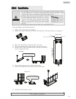
⑤
Connect the battery connectors.
⑥
Verify that Forced Bypass is set to “Inverter”.
⑦
Attach two battery covers.
⑧
Attach three front panels.
⑨
Remove the battery breaker cover on the back panel of the UPS.
⑩
Set BATT MCCB to “ON”.
This completes the battery connector connection.
M
CCB
⑥
Forced Bypass switch should be inverter
position.
⑦
Insert the tabs on the left and right sides
of the battery cover into the slots and
press it down until you hear a click
sound. Secure with the screws.
⑧
Place the front cover
over the battery cover,
and press it down.
⑤
The connector cannot be inserted
in the wrong orientation. Check
the correct insert orientation, and
push in until you hear a click.
⑧
First catch the claws on the top side,
then push the bottom side in.
⑨
Remove the screws, and
remove the breaker cover.
⑩
Set BATT MCCB to “ON”.
The removed cover is reattached in §10
“
Checking before installation
”
.
Leave it removed. Do not lose the screws and cover.
Notes
A
A
1
1
1
1
H
H
2
2
0
0
2
2
U
U
A
A
1
1
1
1
H
H
3
3
0
0
2
2
U
U
Summary of Contents for A11H
Page 1: ...Instruction Manual 120V Model 2kVA 3kVA Uninterruptible Power Supply M0008068...
Page 70: ...Blank page...
Page 71: ...Blank page...
Page 72: ......


