Installation and Wiring
16
If the UPS cannot be securely fixed to the floor with the level adjusters, use floor securing brackets (option). In such a case,
consider maintenance space before fixing the UPS to the floor. For the installation procedure, see the instruction manual of the
floor securing brackets. For details on floor securing brackets, contact your supplier or SANYO DENKI.
The cables are connected between the UPS units at the time of shipment. If the cables were disconnected upon customer request
for transportation and installation, be sure to perform the wiring work properly. For details on wiring between UPS units and the
power distribution unit, see §6.3 “Connection Between Units.”
§
6
6
.
.
2
2
I
I
n
n
s
s
t
t
a
a
l
l
l
l
i
i
n
n
g
g
U
U
P
P
S
S
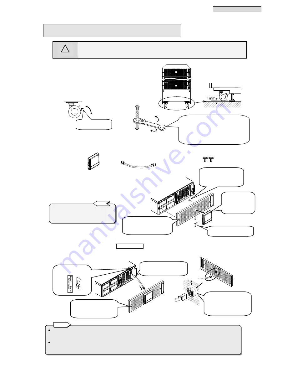
CAUTION
!
Be sure to lock the casters on the bottom of the UPS, and adjust the level adjusters to fix the UPS so
that it is not tilted and does not wobble. If the UPS is not securely fixed, shock and vibration from,
for example, an earthquake may cause the UPS to shift or fall, possibly resulting in bodily injury.
After you open the package, install the UPS as is,
and then attach the LCD panel.
①
Move the UPS to the installation location.
②
Lock the casters in four places.
③
Fix the UPS in place with the level adjusters in four places.
④
Check that the UPS is securely fixed in place.
⑤
Prepare the LCD panel, LCD panel connection cable, and two screws A
for securing the LCD panel (only when securing the LCD panel) that are
supplied with the UPS.
⑥
Remove the front panel from the UPS unit to which the LCD panel is
to be attached.
Remove the logo plate, and attach the LCD panel.
The LCD panel is secured by magnets, but also secure it with the
screws A in two places if there is the risk of it falling off.
⑦
Insert one end of the LCD panel connection cable into the connector at the position shown in the diagram.
⑧
Check that the forced bypass switch
Forced Bypass
above the connector is set to the “
Inverter
” side.
⑨
Insert the other end of the cable connected in step 7 into the connector on the back of the front panel.
⑩
Secure the front panel with screws in the two places on the left and right.
③
Adjust the height of the level adjusters in
four places so that the UPS is not tilted
and does not wobble. Use a wrench (M10:
for hexagonal bolts) to turn the adjusters
in the direction indicated by A in the
diagram until the casters are raised
approximately 1 mm from the floor.
A
B
Lock
Release lock
Notes
②
Lock the caster
with the lock.
Level adjuster
Side
Caster
Screw A: For securing LCD
panel M3×6 2
LCD Panel 1
LCD Panel Connection Cable 1
Pinch the tabs on the back,
and remove the logo plate.
Insert the connector
parts on the back of
the LCD panel into
the holes on the
front panel.
From the back side of the
front panel, secure the two
places at the back of the
LCD panel with screws A.
The LCD panel can be attached to any UPS
unit. Attach it to the UPS unit that is in an
easy to operate position, depending on the
installation state of the UPS units.
T i p
⑧
Is the switch set the
“
Inverter
" side?
⑨
Check the insertion
orientation of the connector.
The connector cannot be
inserted if it is not oriented
properly.
⑩
Use a screwdriver to
tighten the screws in two
places on the left and right
to secure the front panel.
Use a screwdriver to loosen the
screws in the two places on the
left and right, and then remove
the front panel.
⑦
Insert one end of the
connection cable into the
connector.
(0.04 in)


