background image

7

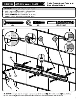
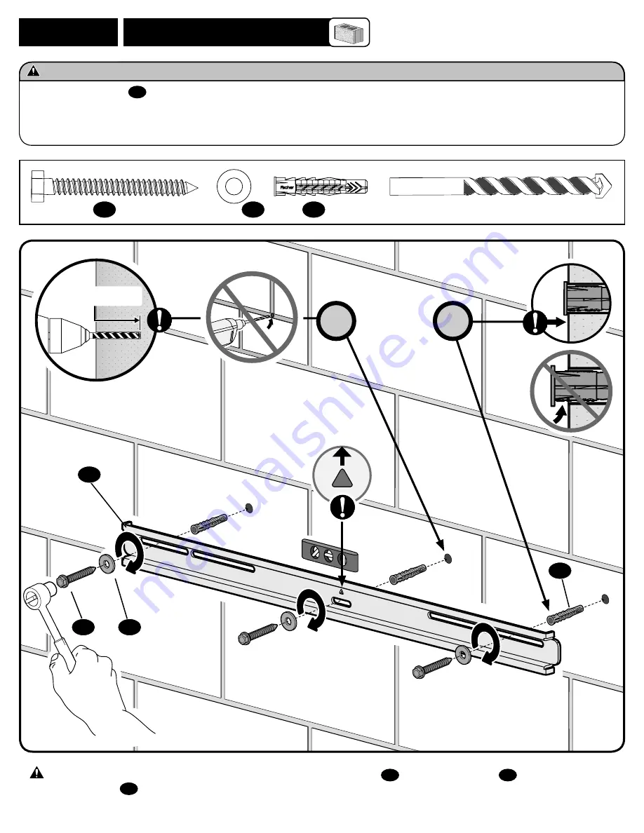
STEP 2B    ATTACH WALL PLATE

Solid Concrete or Concrete 

Block Installation


Mount the wall plate


06

 directly onto the concrete surface


Minimum 

solid concrete

 thickness: 8 in. (20.3 cm).    


Minimum 

concrete block

 size: 8 x 8 x 16 in. (20.3 x 20.3 x 40.6 cm)


Minimum horizontal space between fasteners: 8 in. (20 cm)


CAUTION: 

Avoid potential personal injury or property damage!


CAUTION:

 Avoid potential personal injury or property damage! Tighten lag bolts 

07

 ONLY until the washers 

08

 are pulled firmly 

against the wall plate 

06

. Ensure the wall plate is SECURELY fastened to the wall before continuing on to the next step.

08

09

06

07

3 in. (75 mm)

07

08

09

3/8 in. (10 mm)

3X

3X

Summary of Contents for CILT3

Page 1: ...NT INSTRUCTIONMANUAL We ll Make It Stress Free If you have any questions along the way just give us a call 1 800 359 5520 We re ready to help NOTE TO INSTALLER Pleaseleavethis manualwiththe homeowner Texto en español página 12 ...

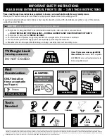
Page 2: ...ANUS com or call customer service to find a compatible mount Call Customer Service Tools Needed Wall Construction ONLY install on these acceptable wall types Unsure 125 lbs 56 6 kg Drywall alone will NOT hold the weight of your TV wood studs Solid concrete or concrete block ACCEPTABLE ACCEPTABLE CAUTION DO NOT install in drywall alone Wood Stud Install Concrete Install Pencil Level Stud Finder Scr...

Page 3: ...X 3 94in 100mm MIN 2 00in 50 8mm 29 28in 743 8mm 3 01in 76 4mm 4 00in 101 6mm 16 00in 406 4mm 24 00in 609 6mm 30 51in 775mm 17 25in 438 1mm 3 31in 84mm 2deg ROLL 0 92in 23 5mm TV INTERFACE WALL PLATE TOP VIEW TV MOUNTED TOP VIEW FULLY ASSEMBLED MOUNT 10deg TILT SIDE VIEW ...

Page 4: ...forestartingassembly verifyallpartsareincluded andundamaged Ifanypartsaremissingordamaged donotreturnthedamageditemtoyourdealer contactCustomerService Neverusedamagedparts NOTE Not all hardware included will be used M8 x 30 mm M8 x 25mm M6 x 12mm M6 x 20mm M8 x 40mm M8 x 45mm M8 x 50mm 2 5mm 22mm M6 x 35mm M8 x 35mm M8 x 20mm M8 x 16mm Parts and Hardware for STEP 1 TV Screws qty 4 each Only one si...

Page 5: ...NG will damage the TV Too Short Correct Too Long ATTACH TV BRACKET TO TV STEP 1 Flat Back TV TV brackets lay flat on your TV NO SPACER SPACER NEEDED Flat Back TV with Extra Space Needed for deep inset holes or cable interference Rounded or Irregular Back TV TV brackets NOT resting flat on your TV A B 03 03 02 02 01 01 01 02 04 05 NO SPACER A 01 02 SPACER NEEDED B 03 02 01 NOTE Combine spacers if n...

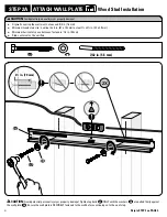
Page 6: ... x 4 in 51 x 102 mm actual 11 2 x 31 2 in 38 x 89 mm Minimum horizontal space between fasteners 16 in 40 cm Stud centers must be verified CAUTION Avoid potential personal injury or property damage Tighten lag bolts 07 ONLY until the washers 08 are pulled firmly against the wall plate 06 Ensure the wall plate is SECURELY fastened to the wall before continuing on to the next step 08 06 07 2 in 70 mm...

Page 7: ...3 x 20 3 x 40 6 cm Minimum horizontal space between fasteners 8 in 20 cm CAUTION Avoid potential personal injury or property damage CAUTION Avoid potential personal injury or property damage Tighten lag bolts 07 ONLY until the washers 08 are pulled firmly against the wall plate 06 Ensure the wall plate is SECURELY fastened to the wall before continuing on to the next step 08 09 06 07 3 in 75 mm 07...

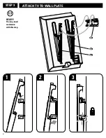
Page 8: ...8 ATTACH TV TO WALL PLATE STEP 3 HEAVY You may need assistance with this step 3 2 1 05 04 06 ...

Page 9: ...and hold the release cords R down while pulling the TV away from the wall 2 Temporarily rest the TV on the kick stands K while connecting the cables to the TV CAUTION TV is not secured to the wall when it is in the kick stand K position Assistance is recommended for this step 3 Lift the kick stands K up while holding the TV 4 Gently rest the TV back until the brackets click and lock the TV in plac...

Page 10: ...ey 10 to raise or lower that respective side of the TV Raise Lower 10 Loosen Tighten Your TV should adjust easily when moved then stay in place If your TV is too loose or too tight adjust the tension knobs T using hex key 10 NOTE Once your TV is in place tighten the tension knobs T to prevent unwanted movement 10 T L ...

Page 11: ...while gently pulling the bottom of the TV away from the wall until the kick stands K fall into place CAUTION To prevent breaking the locking latch always pull and hold the release cords R down while pulling the TV away from the wall 2 Rest the TV on the kick stands K while disconnecting the cables from your TV 3 Lift TV up and off the wall plate to remove To reattach your TV Follow the procedures ...

Page 12: ...ame a nuestro servicio técnico PRECAUCIÓN Evite posibles lesiones personales y daños materiales Este producto se ha diseñado para su uso en montantes de madera hormigón macizo y paredes de bloques de hormigón NO lo instale en paredes únicamente de yeso Este producto está diseñado SOLO PARA USO EN INTERIORES La pared debe ser capaz de soportar hasta cinco veces el peso combinado del televisor y la ...

Page 13: ...tención al cliente Nunca utilice piezas deterioradas PÁGINA 4 PRECAUCIÓN Evite lesiones personales y daños materiales El yeso que recubre la pared no debe exceder los 16 mm 5 8 Tamaño mínimo del montante de madera nominal 51 mm x 102 mm 2 x 4 actual 38 mm x 89 mm 1 x 3 Espacio horizontal mínimo entre los elementos de sujeción 40 cm 16 Debe comprobar los montantes centrales TV con parte posterior p...

Page 14: ...del bloque de cemento 203 x 203 x 406 mm 8 x 8 x 16 Espacio horizontal mínimo entre los elementos de sujeción 30 cm 12 1 Jale hacia abajo y sostenga ambos cordones de desenganche R mientras tira con cuidado de la parte inferior del televisor para separarlo de la pared hasta que los pies de apoyo K se ubiquen en su lugar PRECAUCIÓN Para que el pasador de seguridad no se rompa siempre jale y sosteng...

Page 15: ...ugar PRECAUCIÓN Para que el pasador de seguridad no se rompa siempre jale y sostenga los cordones de desenganche R mientras retira el televisor de la pared 2 Apoye el televisor sobre los pies de apoyo K mientras desconecte todos los cables en el televisor 3 Tire de la parte inferior del televisor desde la pared lo suficiente como para inclinar el televisor hacia arriba y fuera de la placa mural 06...

Page 16: ...NUS com IT S TIME TO SHOW OFF Register your new mount to make the most of your SANUS warranty Visit SANUS com to register now it takes 25 seconds When you share your handiwork with your friends tag sanusspaces for a chance to be featured on SANUS com sanussystems SanusSystems pinterest com SANUS SanusSystems 6901 602480 00 ...

Reviews: