background image

14

Manage Cables

Single shelf configuration

Cables can be routed through the opening in the lower back of 
the wall plate 

06

.

For stacked configurations, cables can be routed through the 
inside of the wall plates 

06

. When you are done routing cables 

replace the top (T) and front (F) covers.

Stacked configurations

STEP 3

06

(F)

(T)

Summary of Contents for FPA400

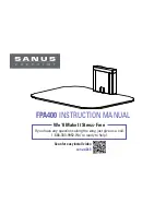
Page 1: ...FPA400 INSTRUCTION MANUAL Scan for easy install video san us 260 We ll Make It Stress Free If you have any questions along the way just give us a call 1 888 333 9952 We re ready to help ...

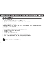
Page 2: ...ave doubts about the safety of the installation assembly or use of this product contact Customer Service or call a qualified contractor CAUTION Avoid potential personal injuries and property damage Do not use this product for any purpose not explicitly specified by manufacturer Do not place objects heavier than 15 lb 6 8 kg on shelf Do not place a TV on shelf Do not allow children to climb or hang o...

Page 3: ... in 11 mm 7 16 in 3 mm 1 8 in 10 mm 3 8 in Weight Limit 15 lb 6 8 kg DO NOT EXCEED Features Can be mounted to drywall wood stud or concrete Stackable to accommodate multiple components not to exceed 15 lb 6 8 kg on each shelf ...

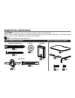
Page 4: ... verify all parts are included and undamaged If any parts are missing or damaged do not return the damaged item to your dealer contact Customer Service Never use damaged parts Parts and Hardware for STEP 1 Parts and Hardware for STEP 2 Lag Bolts and Wall Screws Washer Wall Plate Wall Anchors 01 02 04 05 09 10 11 03 1 3 3 1 1 1 1 2 2 1 1 06 07 08 1 4 x 2 in 8 x 2 in M5 x 20 M5 x 6 M3 ...

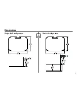
Page 5: ...5 Dimensions Single shelf configuration 1 11 28 1 6 3 159 9 12 50 317 5 17 00 431 8 Stacked configuration 1 11 28 1 5 11 129 8 6 3 159 9 12 50 317 5 17 00 431 8 in mm ...

Page 6: ... of the stud using an awl a thin nail or an edge to edge stud finder CAUTION Avoid potential personal injuries and property damage Drywall covering the wall must not exceed 16 mm 5 8 in Minimum wood stud size common 51 x 102 mm 2 x 4 in nominal 38 x 89 mm 1 x 3 in 2 Remove the front F and top T covers from the wall plate 06 Level the wall plate 06 and mark the hole locations F T ...

Page 7: ...lled to a depth of 63 5 mm 2 in using a 3 mm 1 8 in diameter drill bit 4 Tighten the lag bolt 01 and washer 03 the screw 02 only until they are pulled firmly against the wall plate 06 CAUTION Improper use could reduce the holding power of the lag bolt and screw DO NOT over tighten the lag bolt and screw ...

Page 8: ...ations Level the wall plate 06 and mark the hole locations CAUTION Avoid potential personal injuries and property damage Mount the wall plate 06 directly onto the concrete surface Minimum solid concrete thickness 203mm 8 in Minimum concrete block size 203 x 203 x 406 mm 8 x 8 x 16 in 2 Drill pilot holes IMPORTANT Pilot holes must be drilled to a depth of 75 mm 3 in using a 10 mm 3 8 in diameter dr...

Page 9: ... concrete surface 4 Tighten the lag bolt 01 and washer 03 the screw 02 only until they are pulled firmly against the wall plate 06 CAUTION Improper use could reduce the holding power of the lag bolt and screw DO NOT over tighten the lag bolt and screw 3 4 06 04 05 03 01 02 04 STEP 1 ...

Page 10: ...Level the wall plate 06 and mark the hole locations CAUTION Avoid potential injuries or property damage Mount the wall plate 06 directly onto the wall Drywall covering the wall must not exceed 13mm 1 2 in Do not install anchors into the seam between drywall pieces 2 Drill pilot holes IMPORTANT Pilot holes MUST be drilled to a depth of 38 mm 1 in using a 10 mm 3 8 in diameter drill bit F T ...

Page 11: ...4 CAUTION Be sure the anchors are seated flush with the surface 4 Tighten the screws 02 only until they are pulled firmly against the wall plate 06 CAUTION Improper use could reduce the holding power of the screw DO NOT over tighten the screws 04 04 ...

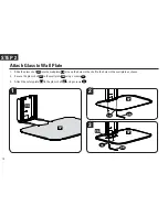
Page 12: ... the holes in the shelf to the holes in the wall plate as shown 2 Secure the glass shelf 07 to the wall plate 06 using screws 10 3 Attach the safety plate 08 to the glass shelf 07 using screws 11 1 2 3 STEP 2 Attach Glass to Wall Plate 09 09 10 11 07 07 07 06 08 ...

Page 13: ...13 ...

Page 14: ...outed through the opening in the lower back of the wall plate 06 For stacked configurations cables can be routed through the inside of the wall plates 06 When you are done routing cables replace the top T and front F covers Stacked configurations STEP 3 06 F T ...

Page 15: ...15 ...

Page 16: ...e atención al cliente o llame a un técnico calificado PRECAUCIÓN Evite posibles lesiones personales y daños materiales No utilice este producto para ningún otro propósito que no sea el explícitamente especificado por el fabricante No coloque objetos que superen los 6 8 Kg 15 libras en la repisa No coloque un televisor en la repisa No permita que los niños se trepen o se cuelguen de la repisa El fabr...

Page 17: ...es Verifique el centro del montante con un punzón o un clavo delgado o bien utilice un detector de bordes de montantes PRECAUCIÓN Evite posibles lesiones personales y daños materiales El material que recubre la pared no debe exceder los 16 mm 5 8 pulgada Tamaño mínimo del montante de madera común 51 mm x 102 mm 2 x 4 pulgadas nominal 38 mm x 89 mm 1 x 3 pulgadas 2 Retire las cubiertas frontal F y s...

Page 18: ...l 06 directamente sobre la pared El material que recubre la pared no debe exceder los 13 mm 1 2 pulgada No instale anclajes en la juntura entre las piezas de yeso Fijar la placa mural a la pared Opción para hormigón sólido o bloques de cemento IMPORTANTE Para las configuraciones apiladas comience a apilar de arriba a abajo Retire las cubiertas frontal F y superior T de la placa mural 06 1 Nivele la...

Page 19: ...Deslice la repisa de vidrio 07 en la placa mural 06 Alinee los orificios de la repisa con los orificios de la placa mural tal como se ilustra 2 Fije la repisa de vidrio 07 a la placa mural 06 con tornillos 10 3 Coloque la placa de seguridad 08 a la repisa de vidrio 07 usando tornillos 11 Fijar el vidrio a la placa mural PASO 3 Organización de cables Configuración con una sola repisa Los cables puede...

Page 20: ...o representation of warranty expressed or implied regarding the information contained herein Milestone assumes no responsibility for accuracy completeness or sufficiency of the information contained in this document 2013 Milestone AV Technologies All rights reserved Sanus is a division of Milestone All other brand names or marks are used for identification purposes and are trademarks of their respe...

Reviews: