background image

4

1

2

≤ 16 mm

(5/8 in.)

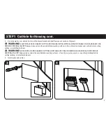
STEP 1  Cut Hole for Housing

01


CAUTION:


Avoid potential personal injuries and property damage!


ƕ

Drywall covering the wall must not exceed 16 mm (5/8 in.).


ƕ

Box must be mounted between studs that are at least 406 mm (16 in.) apart. After installation there will not be enough space between the 
SA809 and the studs for electrical wires/cables, plumbing, ductwork, or insulation. Choose your SA809 location carefully.

1.  Locate the studs using an edge-to- edge stud finder. Verify the edges of the studs using an awl or thin nail. Mark the edges of the studs 

with pencil.

2.  Center the template 

01

 between the two studs. Level the template 

01

 and use a pencil to mark the open area of the template 

01

.

Summary of Contents for SA809

Page 1: ...SA809 INSTRUCTION MANUAL We ll Make It Stress Free If you have any questions along the way just give us a call 1 800 359 5520 We re ready to help Scan for more information san us 448 ...

Page 2: ...lease read through these instructions completely to be sure you re comfortable with this easy install process If you do not understand these instructions or have doubts about the safety of the installation assembly or use of this product contact Customer Service at 1 800 359 5520 UK 0800 056 2853 CAUTION Avoid potential personal injuries and property damage ƕ Do not use this product outdoors ƕ Thi...

Page 3: ...y all parts are included and undamaged If any parts are missing or damaged do not return the damaged item to your dealer contact Customer Service Never use damaged parts Supplied Parts STEP 1 Parts STEP 2 Parts STEP 3 Parts 04 05 2 06 ECO Mini Bracket Component Panel Elastic Velcro Strap Cover 01 Template 02 03 Housing ...

Page 4: ... installation there will not be enough space between the SA809 and the studs for electrical wires cables plumbing ductwork or insulation Choose your SA809 location carefully 1 Locate the studs using an edge to edge stud finder Verify the edges of the studs using an awl or thin nail Mark the edges of the studs with pencil 2 Center the template 01 between the two studs Level the template 01 and use ...

Page 5: ...PERSONAL INJURY Always make certain the area behind mounting surfaces is free of electrical wires and cables before cutting drilling or installing fasteners WARNING EXPLOSION AND FIRE HAZARD CUTTING OR DRILLING INTO GAS PLUMBING CAN CAUSE DEATH OR SERIOUS PERSONAL INJURY Always make certain the area behind mounting surfaces is free of gas water waste or any other plumbing before cutting drilling o...

Page 6: ...l outlet box not included capable of attaching to the SA809 housing 02 following the instructions included with the outlet box NOTE Knockouts are provided for ease of installation Any unused knockouts that have been punched are to be closed up with a metal plug 2 Carefully fit the housing 02 into the cutout section of the wall ...

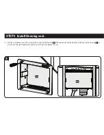
Page 7: ...tall Housing cont 02 02 3 Using a screwdriver turn the screws in the corners of the housing 02 These will raise the locking tabs in the rear of the housing 02 to secure it to the wall Tighten only until secure Do not over tighten screws ...

Page 8: ...mmunication Equipment shall be maintained for safe operation of the equipment when installed in accordance with the National Electric Code ANSI NFPA 70 1999 Refer to communication equipment manufacturer s specifications for minimum spacings 1 To use the ECO Mini purchased separately in the SA809 first remove feet 2 Fit the ECO Mini into the ECO Mini bracket 03 supplied with the SA809 2 03 ...

Page 9: ... with the SA809 Optional 3 3 Use two of the screws from the feet to secure the ECO Mini in the bracket 03 4 Slide the ECO Mini and bracket 03 into the top of the housing 02 Lock the bracket 03 into the housing 02 by sliding it towards the corner until you feel it catch 03 ...

Page 10: ...straps 05 to attach components to the front of the component panel 04 and to secure wires to the back of the panel NOTE Zip ties can also be used by looping them through the holes of the component panel 04 to secure components to the component panel 04 05 05 05 05 ...

Page 11: ...2 02 6 To mount the component panel 04 press the component panel 04 into the housing 02 until the side buttons snap into the depressions in the sides of the housing 02 To remove component panel 04 grasp panel in the center and pull straight out ...

Page 12: ...omponents cont 06 02 02 06 7 Install cover 06 by fitting the bottom tabs of the cover 06 into the bottom slots of the housing 02 Press near the upper tabs of the cover 06 to snap them into the upper slots of the housing 02 ...

Page 13: ...all mounts To access the SA809 after installation disconnect all cables and wires from the TV then either slide or remove the arm or TV mount from the wall plate IMPORTANT Check your TV owner s manual to see if there are any special requirements for mounting or removing your TV ...

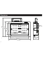
Page 14: ...14 Dimensions 11 40 in 289 6 mm 14 2 in 360 7 mm 8 84 in 224 6 mm 14 07 in 357 5 mm 16 63 in 422 4 mm 3 92 in 99 6 mm 4 00 in 101 6 mm 2 87 in 72 9 mm 0 75 in 19 1 mm ...

Page 15: ...15 ...

Page 16: ...materiales ƕ No utilice este producto al aire libre ƕ Este sistema en la pared es para uso con ITE o Sólo audio equipos Video ƕ La temperatura ambiente máxima especificada del sistema de gabinete es 40o 120 º F 4o 49 º C No utilice este producto para ningún otro propósito que no sea el especificado explícitamente por el fabricante ƕ El fabricante no se responsabiliza por ningún daño o lesión resul...

Page 17: ...car la carcasa Ver página 6 1 Romper con los sectores de la vivienda Opcionalmente instale una lista de UL 120 VAC caja eléctrica de salida no incluido capaz de unirse a la carcasa 02 SA809 siguiendo las instrucciones incluidas en la caja de salida 2 Con cuidado coloque la carcasa 02 en la sección que cortó de la pared 3 Con un destornillador ajuste los tornillos de las esquinas de la carcasa 02 E...

Page 18: ...ntes 04 y átelos para sujetar los componentes del panel 04 6 Para instalar el panel de componentes 04 presiónelo 04 en la carcasa 02 hasta que los botones laterales encajen en los huecos de la carcasa 02 7 Coloque la cubierta 06 Para ello introduzca las lengüetas inferiores de la cubierta 06 en las ranuras inferiores de la carcasa 02 Presione cerca de las lengüetas superiores de la cubierta 06 par...

Page 19: ...19 ESPAÑOL ...

Page 20: ...d Milestone makes no representation of warranty expressed or implied regarding the information contained herein Milestone assumes no responsibility for accuracy completeness or sufficiency of the information contained in this document 2013 Milestone AV Technologies All rights reserved Sanus is a division of Milestone All other brand names or marks are used for identification purposes and are tradem...

Reviews: