Page 29
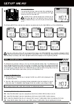
Choosing the Throttle Channel Option, Continued....
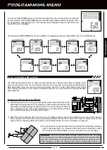
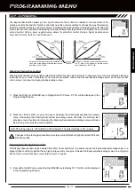
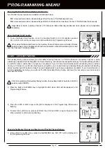
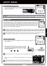
Two Throttle Channel options are available as described below:
TH1
- Exponential and Servo Speed settings affect Channel 1 Throttle servo only.
TH2
- Exponential and Servo Speed settings affect both Channel 1 and Auxiliary Channel 3 Throttle servos equally.
Regardless of choice, Auxiliary Channel 3 Throttle servo Exponential and Servo Speed are not adjustable separately.
[[PROgRaMMing MEnU
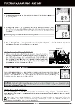
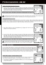
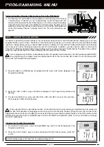
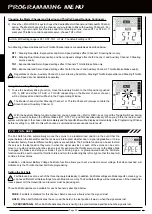
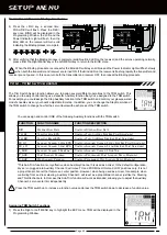
Activating and using the Motor on Axle Mixing Function
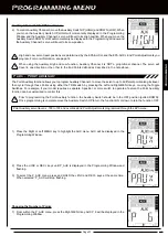
1) To Activate and use the Motor on Axle Mixing function, move the Auxiliary Switch to the ON position (pushed UP). AUX will
flash in the Programming Window and the Power Indicator Light will flash rapidly.
When the Motor on Axle Mixing function is Activated, the following Motor on Axle Mixing options are available during use:
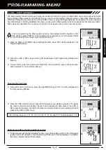
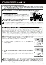
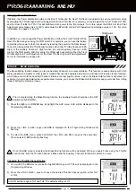
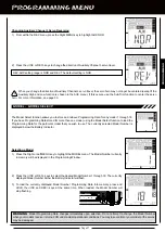
Assigning Auxiliary Channel 3 Throttle Servo Trim to the TRM Switch
1) The TH-TRIM switch affects only the Throttle High and Brake trimming of the
Channel 2 Throttle servo. If desired, you can independently control the Throttle
High and Brake trimming of the Auxiliary Channel 3 Throttle servo. To do this,
assign the Auxiliary Channel 3 Sub-Trim function to the TRM switch. With this
setup, the TH-TRIM switch will control the Channel 2 Throttle servo Trim and the
TRM switch will control the Auxiliary Channel 3 Throttle servo Trim. For more
information, see page 40.
PROGRAMMING
or
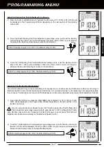
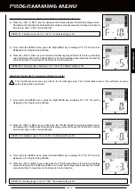
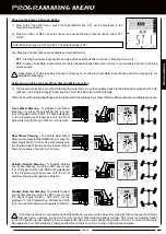
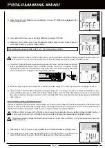
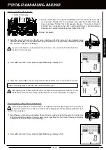
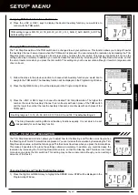
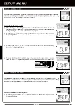
Front Throttle BuRN
- To Activate Front Throttle
Burn, press and HOLD the Right MENU key (or
push and HOLD the Right Toggle Switch). AUX
BURN will be displayed in the Programming
Window. The Front Throttle (Throttle Channel 2)
will return to Neutral and the Rear Throttle (Auxiliary
Channel 3) will work normally.
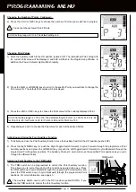
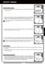
Front Throttle Hold
- To Activate Front Throttle
Hold, press and HOLD the Left MENU key (or
push and HOLD the Left Toggle Switch). AUX
F_HLD will be displayed in the Programming
Window. Only the Rear Throttle (Auxiliary Channel
3) will operate, while the Front Throttle (Throttle
Channel 2) will Hold it's last position.
HOLD
HOLD
FREE
NEUTRAL
FREE
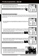
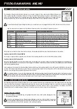
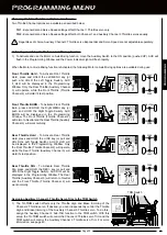
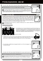
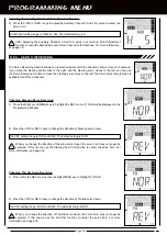
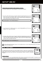
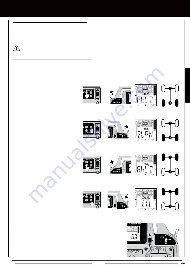
Rear Throttle Hold
- To Activate Rear Throttle
Hold, press and HOLD the +/INC key (or pull and
HOLD the Left Toggle Switch). AUX R_HLD will
be displayed in the Programming Window. Only
the Front Throttle (Throttle Channel 2) will operate,
while the Rear Throttle (Auxiliary Channel 3) will
Hold it's last position.
FREE
HOLD
Rear Throttle DIG
- To Activate Rear Throttle
Dig, press and HOLD the DEC/- key (or pull and
HOLD the Right Toggle Switch). AUX DIG will be
displayed in the Programming Window. The Rear
Throttle (Auxiliary Channel 3) will return to Neutral
and the Front Throttle (Throttle Channel 2) will
work normally.
NEUTRAL
FREE
or
or
HOLD
HOLD
HOLD
HOLD
HOLD
or
HOLD
HOLD
TRM Switch
Summary of Contents for Gemini X
Page 1: ...Page 1 ...
Page 55: ...Page 55 NOTES ...


