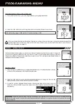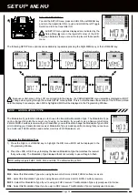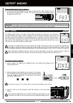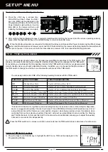
Page 51
inDEX
Symbols
2.4GHz Frequency Band, Precautions 4
+/INC Key, Definition of 48
+/INC Key, Overview 11
A
Activate, Definition of 48
Alarms.
See
Inactivity Alarm
See
Low Voltage Alarm
Antenna - Receiver, Orientation of 4
Antenna Reception Wire - Receiver, Definition of 7, 48
Antenna Reception Wire - Receiver, Diagram of 7
Antenna - Transmitter, Definition of 7, 48
Antenna - Transmitter, Diagram of 6
Antenna - Transmitter, Orientation 6
Audible Key Tone, Definition of 48
Audible Key Tone, Programming 44
Auxiliary High and Low, Definition of 48
Auxiliary High and Low, Overview 22
Auxiliary Switch, Definition of 8, 48
Auxiliary Switch, Diagram of 6
Auxiliary Switch, Using 22
Auxiliary Mixing, Choosing Master Channel Options 31
Auxiliary Mixing, Overview 31
Auxiliary Mixing, Using 32
Auxiliary Programming, Overview 22
B
Batteries - Receiver, Installation 10
Batteries - Transmitter, Installation 9
Battery Cell Count, Choosing Cell Count 46
Battery Cell Count, Low Voltage Alarm 46
Battery Cell Count, Overview 45
Battery Compartment, Definition of 8, 48
Battery Compartment, Diagram of 6
Battery Indicator, Definition of 48
Battery Indicator, Diagram of 11
Battery Plug - Transmitter, Diagram of 10
Bind Button - Receiver, Definition of 8, 48
Bind Button - Receiver, Diagram of 7
Bind Button, Using 14, 39
Binding.
See Also
Transmitter and Receiver Binding
Binding, Definition of 48
Binding, Overview 14, 39
Bind LED 14, 39,
Bind LED, Diagram of 7
Brake Hold.
See
Brake Mixing, Using Brake Hold
Brake Hold, Definition of 48
Brake Mixing, Choosing Throttle Options 30
Brake Mixing, Definition of 48
Brake Mixing, Overview 30
Brake Mixing, Using Brake Hold 31
Brake Side, Definition of 48
Burn.
See Also
Motor on Axle Mixing, Activating and Using
Burn, Definition of 48
C
Charging Jack, Definition of 8, 48
Charging Jack, Diagram of 7
Charging Jack, Using with Optional Charger 9
Coaxial Cable - Receiver, Definition of 8, 48
Coaxial Cable - Receiver, Diagram of 7
D
DEC/- Key, Definition of 48
DEC/- Key, Overview 11
Dig.
See Also
Motor on Axle Mixing, Activating and Using
Dig, Definition of 48
Digital Voltage Indicator, Definition of 48
Digital Voltage Indicator, Diagram of 11
DS2 Modulation, Choosing 38
DS2 Modulation, Definition of 48
E
End Point Adjustment, Assigning to TRM Switch 18
REFERENCE
Summary of Contents for Gemini X
Page 1: ...Page 1 ...
Page 55: ...Page 55 NOTES ...

