Optional Equipment
Safety, Operation and Maintenance Manual - Aug 2012
8-14
SY115C9/135C/155H Crawler Hydraulic Excavator
8. Check the temperature of the hydraulic
oil, which should be cooled down to a safe
temperature. Remove the two screw plugs
from the inlet and outlet. Be careful not to
contaminate the hose connections with any
dirt or soil.
If the O-ring is broken, replace it with a
new one.
9. Connect the hose to the side of the op-
tional equipment.
When connecting the hose, check the oil
flow direction and be careful not to make
any mistakes.
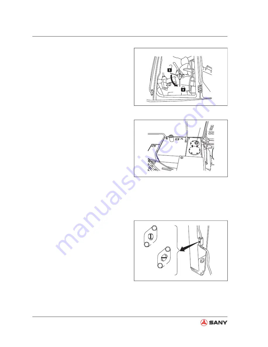
10. Turn the rotor of the stop valve (mounted
to the inlet and outlet lines to the side of
the arm) to FREE position (a).
(a) unlocked: allows
fl
ow of the hydraulic oil
(the arrow-indicated direction is parallel
to the longitudinal direction of arm).
(b) locked: stops
fl
ow of the hydraulic oil (the
arrow-indicated direction is perpendicu-
lar to the longitudinal direction of arm).
11. Check the oil level in hydraulic tank after
installation of the optional equipment.
6. Place the lockout control to LOCK position
(L).
7. The breather valve (F) on top of the
hydraulic tank can be used to release the
internal pressure of the hydraulic lines.
To release the pressure completely, turn
and open the butter
fl
y nut on the breather
valve (F) and press the relief button to re-
lease the pressure.
F
L
CZ335-1105010
F
CZ335-1105011
a
b
CZ335-1105012
Fig. 8-18
Fig. 8-19
Fig. 8-20


