background image

MACHINE CONTROLS

3-23

SY60C Excavator OMM

NOTICE!

If any part of the machine moves when the 
hydraulic lockout control lever is in the locked 
(closed) position, shut down the engine 
immediately.

Contact a SANY dealer to correct this problem.

The hydraulic lockout control lever (1) disables or 
enables the hydraulic function for work equipment, swing 
and travel control, and optional equipment.

Move the hydraulic lockout control lever down to the 
locked (closed) position (3) to disable hydraulic controls.

Joystick Controls

WARNING

Prevent unexpected movement of the machine. 
Know the positions and functions of both 
joysticks before operation. Failure to follow this 
warning could result in death or serious injury.

NOTE: 

There are two operating modes available for the 
joystick controls: the Society of Automotive 
Engineers (SAE) mode and the backhoe loader 
(BHL) mode. The swing and bucket functions are 
the same for the SAE and BHL modes.

Joystick SAE Mode

Left Joystick – SAE Mode

0002767

Figure 3-43

The SAE mode uses the left joystick to control the arm 
and upper structure:

• Swing the upper structure to the left (1)

• Arm out (2)

• Swing the upper structure to the right (3)

• Arm  in  (4)

• Neutral (N)

Right Joystick – SAE Mode

0002765

Figure 3-44

NOTES: 

  • The joystick controls return to the neutral position 

automatically when released. The functions of the 
machine will stop.

  • In longitudinal excavation, rotate the undercarriage 

so that the travel motors are behind the upper 
structure to maximize the stability and lift capacity of 
the machine.

The SAE mode uses the right joystick to control the 
boom and bucket

:

• Bucket dig (1)

• Boom down (2)

• Bucket dump (3)

• Boom up (4)

• Neutral (N)

1

2

3

4

N

4

1

2

3

N

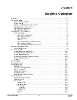
Summary of Contents for SY60C

Page 1: ...service sanyamerica com SANY Part Number SSY005078669 SY60C Excavator Operation and Maintenance Manual ...

Page 2: ...Page Intentionally Blank ...

Page 3: ... and understand all safety precautions and instructions in this manual and the machine labels before operating or maintaining it Failure to follow safety messages could result in death or serious injury Keep this manual with the machine for reference SY60C Excavator ...

Page 4: ...0269 www sanyamerica com Phone 470 552 SANY 7269 Fax 770 632 7820 2019 by SANY All rights reserved No part of this publication may be reproduced used distributed or disclosed except for normal operation and maintenance of the machine as described herein All information included within this publication was accurate at the time of publication Product improvements revisions etc may result in differen...

Page 5: ...ng Motor Identification Plate 1 4 Engine Identification Plate 1 5 Hydraulic Pump Identification Plates 1 5 Travel Motor Identification Plate 1 5 SANY Contact Information 1 6 Record of Serial Number and Dealer Information 1 6 Correction Request Form 1 7 Glossary of Acronyms 1 8 Safety General Safety 2 2 Hazard Alerts in This Manual 2 2 Operator Safety Information 2 2 Mount and Dismount the Machine ...

Page 6: ...3 Monitor 3 4 Daily Maintenance Information Screen 3 4 Maintenance Information Screen 3 5 Home Screen 3 5 Function List Screen 3 7 System Information Screen 3 7 Main Menu Screen 3 8 Operation Information Screen 3 8 Switch Signals Screen 3 9 Joystick Screen 3 9 Machine Configuration Screen 3 10 Failure Codes Screen 3 10 Global Positioning System GPS Information Screen 3 11 Language Selection Screen...

Page 7: ...lade Control Lever 3 26 Boom Swing Control Pedal 3 26 Windshield 3 27 Opening the Windshield 3 27 Closing the Windshield 3 28 Lower Front Windshield 3 29 Climate Control System 3 30 Climate Control Panel 3 30 Climate Control System Operation 3 31 Air Outlet 3 31 Ventilation 3 31 Radio 3 32 Radio Control Panel 3 32 Radio Operation 3 33 Presetting Radio Stations 3 33 Searching Radio Stations 3 33 Ma...

Page 8: ...t 4 11 Starting the Engine 4 12 Idling the Engine 4 13 Cold Weather Engine Starting 4 13 Warm up Operation 4 14 New Machine Break In 4 14 Engine Shutdown 4 14 Inspection after Engine Shutdown 4 15 Moving the Machine 4 16 Machine Moving Precautions 4 16 Directional Arrow 4 16 Travel Control 4 16 Forward Travel 4 16 Backward Travel 4 16 Spot Turning 4 16 To the Left 4 16 To the Right 4 17 Right Turn...

Page 9: ...le Loading 4 28 Leveling Operation 4 28 Operation Precautions 4 28 Park the Machine 4 29 Parking the Machine on a Grade 4 29 Cold Weather Operation 4 30 Operating Fluids in Cold Weather 4 30 Battery in Cold Weather 4 30 After Daily Operation 4 30 Machine Storage in Cold Weather 4 30 After the Cold Season 4 30 Long Term Storage 4 31 Prepare for Long Term Storage 4 31 During Storage 4 31 Removing fr...

Page 10: ...5 8 Fluid Capacities 5 8 Maintenance Schedule 5 9 Daily Maintenance and Inspection 5 9 When Required 5 9 After the First 50 Hours 5 9 Weekly or Every 50 Hours 5 9 Every 100 Hours 5 9 Every 250 Hours 5 9 Every 3 Months or 500 Hours 5 9 Every 6 Months or 1000 Hours 5 10 Annually or Every 2000 Hours 5 10 Hydraulic Breaker Maintenance Interval 5 10 After Maintenance is Completed 5 10 Lubrication and M...

Page 11: ...or Belt Tension 5 24 Replace the Ventilation Filter 5 25 Check Climate Control System Operation 5 25 Fuel System 5 25 Bleed the Fuel System 5 25 Drain the Fuel Tank 5 25 Replace the Secondary Fuel Filter 5 26 Replace the Fuel Water Separator Filter Element 5 26 Batteries 5 27 Check the Batteries 5 27 Remove the Batteries 5 28 Hydraulic System 5 29 Check the Accumulator Function 5 29 Relieve Hydrau...

Page 12: ...od End Pin 5 42 Bucket Linkage Pins 5 43 Bucket Cylinder Rod End Pin 5 43 Bucket Cylinder Base End Pin 5 43 Cab 5 44 Inspect the Cab Door Lock and Front Window Lock Catch 5 44 Inspect and Lubricate the Cab Door Hinges and Front Window Slide Rail 5 44 Inspect and Tighten the Windshield Wiper Arm Nut 5 44 Bucket 5 45 Replace the Bucket Teeth 5 45 Remove and Install the Bucket 5 46 Specifications Mac...

Page 13: ... 3 Maintenance 1 3 Specifications 1 3 Optional Equipment 1 3 Machine Applications 1 3 Machine Directions 1 3 Serial Number Location 1 4 Product Identification Plate 1 4 Frame Serial Number 1 4 Swing Motor Identification Plate 1 4 Engine Identification Plate 1 5 Hydraulic Pump Identification Plates 1 5 Travel Motor Identification Plate 1 5 SANY Contact Information 1 6 Record of Serial Number and De...

Page 14: ...ls and operation of the machine Point out possible hazardous situations when operating or maintaining the machine Increase machine efficiency during operation Prolong the service life of the machine Reduce maintenance costs Continuing improvements in the design of this machine can lead to changes which may not be covered in this manual Contact a SANY dealer for the latest available information on ...

Page 15: ... detailed prestart checks operating procedures end of day checks and storage information Maintenance This section provides routine maintenance procedures and fluid specifications Specifications This section provides general dimensions and weight of the machine and systems components performance information Optional Equipment This section provides information on the optional equipment that can be u...

Page 16: ...1 2 The identification plate is on the lower front of the cab Frame Serial Number 0002814 Figure 1 3 The frame serial number is stamped on the front of the travel carriage frame Swing Motor Identification Plate 0002815 Figure 1 4 The identification plate is on the top of the swing motor East Huancheng Road Kunshan Development Zone Jiangsu China HYDRAULIC EXCAVATOR SANY HEAVY MACHINERY LIMITED MODE...

Page 17: ...pump Travel Motor Identification Plate 0002812 Figure 1 7 An identification plate is on each travel motor Remove the cover plates to access the travel motors MODEL OUTPUT DISPLACEMENT MADE IN JAPAN kW min 1 ENGINE NO CN 100176 Beijing AL A10V 0 71 DFLR 31R VSC42N00 S4518 MNR R902481204 SN 60800000 vg 71 Made in China DR FR 17bar LR 29kW ROTA TION bar cm3 n 2100min 1 FD 17W33 CN30 Rexroth HYDRAULIC...

Page 18: ...e 470 552 SANY 7269 Fax 770 632 7820 Record of Serial Number and Dealer Information Use this table to record the product information related to this machine Machine Serial No Engine Serial No Right Travel Motor Serial No Left Travel Motor Serial No Swing Drive Motor Serial No Hydraulic Pump Serial No Dealer Name Address Phone Numbers ...

Page 19: ...ge complete the form below and send it to SANY Correction Request Form Date of This Notification Your Name Company Name Department Street Address City State and ZIP Postal Code Phone E mail Machine Model and Serial No Description of Problem wrong information unclear or erroneous procedure etc Corrective Action Taken if any ...

Page 20: ... HEST High Exhaust System Temperatures ISO International Organization for Standardization LCD Liquid Crystal Display OEM Original Equipment Manufacturer OSHA Occupational Safety and Health Administration PPE Personal Protective Equipment PQR Procedure Qualification Report ROPS Rollover Protective Structure SAE Society of Automotive Engineers SCA Supplemental Coolant Additive SDS Safety Data Sheet ...

Page 21: ...Diesel Engine Exhaust 2 4 Machine Decals 2 4 Maintenance Safety 2 5 Lockout Tagout Procedure 2 5 Cleaning the Machine 2 5 Fluid Systems 2 5 Adding Fluids to the Machine 2 5 Refueling 2 5 High Pressure Fluid Lines 2 5 Accumulator 2 6 Electrical System 2 6 Battery Safety 2 6 Disconnect the Battery 2 6 Job Safety 2 6 Personal Protective Equipment PPE 2 6 Hearing Protection 2 6 Travel and Operation Pr...

Page 22: ...erating this machine Only qualified personnel who have been specifically trained on this machine are permitted to operate and or work on this machine The seat belt must be worn by the operator at all times Operator aids such as warning lights horns or buzzers along with displays on the monitors are designed to alert the operator to potential problems Sole reliance on these operator aids in place o...

Page 23: ...sed for grading slope trimming lifting breaking demolishing and trenching SANY assumes no responsibility for any consequence caused by use outside this specified range Unauthorized Use of This Machine Unauthorized uses include but are not limited to the following Transporting people on the machine or in the cab Overloading the machine beyond its capacity Unauthorized Machine Modifications Do not p...

Page 24: ...ing operation or travel Keep all guards in place on the machine Never remove the side window of the machine If this window becomes damaged or broken replace it immediately Block off the area where the machine is being operated and keep all unnecessary personnel out of the work area Diesel Engine Exhaust WARNING CALIFORNIA PROPOSITION 65 WARNING Diesel engine exhaust and some of its constituents ar...

Page 25: ... close all openings using caps and plugs If any fuel or oil fluids leak clean up immediately When installing high pressure hoses make sure they are not twisted Damaged hoses are dangerous and should be replaced Take extreme caution when installing hoses for high pressure circuits Make sure fittings are correctly installed and tightened When assembling or installing parts always tighten them to the...

Page 26: ... machine Never leave the machine running while it is unattended Always park the machine in a safe level area lower any work equipment to the ground lock the controls and secure the machine to prevent tampering by unauthorized personnel Shut down the engine before exiting the machine Before starting any work operations travel or maintenance procedures make sure all personnel are a safe distance fro...

Page 27: ...id any rapid movement acceleration or quick stopping Always be aware of the increased stopping distance required on these surfaces Avoid deep snow or frozen bodies of water Even a slight incline may cause the machine to slip Be extra careful when working on an inclined surface covered with snow or ice When traveling or moving the machine on a snow covered incline allow the machine to come to a sto...

Page 28: ...en without direct contact with the machine s structure Avoid direct contact with high voltage power lines while operating High voltage contact could result in equipment damage death or serious injury Stay clear of overhead power lines they are an electrical hazard Treat all overhead power lines as being energized and not insulated Be sure all underground utilities have been marked before excavatin...

Page 29: ... 13 Quick Coupler Control Screen 3 13 Date and Time Setup Screen 3 14 System Unlocked Screen 3 14 Reserved Function 3 14 Diesel Particulate Filter DPF Screens 3 14 Switches 3 17 Horn Button 3 18 Auxiliary Hydraulic Switch 3 18 Work Light Switch 3 18 Windshield Wiper Switch 3 18 Windshield Washer Switch 3 19 Emergency Stop Switch 3 19 Key Switch 3 19 Throttle Control Dial 3 20 Travel Alarm Switch 3...

Page 30: ...Closing the Windshield 3 28 Lower Front Windshield 3 29 Climate Control System 3 30 Climate Control Panel 3 30 Climate Control System Operation 3 31 Air Outlet 3 31 Ventilation 3 31 Radio 3 32 Radio Control Panel 3 32 Radio Operation 3 33 Presetting Radio Stations 3 33 Searching Radio Stations 3 33 Manual Tuning 3 33 Automatic Tuning 3 33 Sound Mode Adjustment 3 34 Time Adjustment 3 34 Antenna 3 3...

Page 31: ...3 1 1 2 3 4 5 6 7 8 12 11 10 13 14 15 16 17 9 1 Arm cylinder 10 Idler 2 Boom 11 Dozer blade 3 Boom swing cylinder 12 Dozer blade cylinder 4 Cab 13 Boom pivot 5 Sprocket 14 Boom cylinder 6 Track roller 15 Bucket 7 Track 16 Arm 8 Carrier roller 17 Bucket cylinder 9 Track frame ...

Page 32: ...splays the Daily Maintenance Information screen The checklist steps 1 7 should be completed before starting the machine See Prestart Checks and Adjustments on page 4 5 Start the machine and warm up before operating the engine and hydraulic system checklist step 8 See Starting the Engine on page 4 12 Press the button below the check mark icon 1 to confirm all checks and procedures have been complet...

Page 33: ... pause icon 1 to pause or continue the display of maintenance information screens Press the button below the check mark icon 2 to confirm completion of maintenance displayed on the screen When prompted to reset the maintenance icon on the home screen enter the password 53188 to clear the maintenance prompt Press the button below the return icon 3 to return to the previous screen Home Screen 000307...

Page 34: ...e coolant temperature is high the icon illuminates as a warning 11 Function list folder icon Press the button below the icon to access the function list screen 12 High Low travel speed icon Press the button below the icon to select high travel speed rabbit icon or low travel speed turtle icon 13 Auto idle icon Press the button below the icon to enable or disable the auto idle function The auto idl...

Page 35: ...further information Reserved Function Not used at this time reserved for future function Press the button below the left right arrow icon 1 to scroll to and illuminate the selected icon Press the button below the regeneration icon 2 to begin the regeneration cycle See Diesel Particulate Filter DPF Screens on page 3 14 Press the button below the check mark icon 3 to confirm the selected icon Press ...

Page 36: ...ection Select the language that displays information on all display screens Maintain Table Displays when the machine is due for maintenance If maintenance is not due the Maintain Table screen will not open The Maintain Table screen is also used to reset the service timer Press the button below the left right arrow icon 1 to scroll to and illuminate the selected icon Press the button below the gear...

Page 37: ...icon 1 to scroll to the next active machine function page Press the button below the return icon 2 to return to the Main Menu screen Joystick Screen 0003814 Figure 3 11 The Joystick screen displays real time joystick control valve information Press the button below the up down arrow icon 1 to scroll to the next active machine function page Press the button below the return icon 2 to return to the ...

Page 38: ... the return icon 1 to return to the previous screen Failure Codes Screen 0003822 Figure 3 13 The Failure Codes screen is accessed from the Main Menu screen When a failure occurs the failure information icon will change color to blue and the failure code will be displayed on the home screen The Failure Codes screen displays possible failure codes Press the button below the return icon 1 to return t...

Page 39: ...reen 0003820 Figure 3 15 The Language Selection screen is accessed through the Main Menu screen The Language Selection screen allows the selection of the language that will display information on all display screens To change the language setting Press the button below the up down arrow icon 1 to select the desired language Press the button below the check mark icon 2 to confirm the selected langu...

Page 40: ... page Press the button below the check mark icon 11 to confirm the selected work tool Press the button below the return icon 12 to return to the previous screen Flow Rate Information Screen 0003815 Figure 3 17 NOTE Check the work tool operator manual for hydraulic flow rate information and follow all optional equipment information and safety precautions The Flow Rate Information screen displays th...

Page 41: ... the bar graph which will lower the flow rate Press the button below the check mark icon 4 to confirm the flow rate adjustment Press the button below the return icon 5 to return to the previous screen Quick Coupler Control Screen 0003829 Figure 3 19 The Quick Coupler Control screen allows the operator to lock and unlock the quick coupler Press the button below the active icon 4 to activate the qui...

Page 42: ...stem Unlocked Screen SANY factory and authorized service only Reserved Function Not used at this time reserved for future function Diesel Particulate Filter DPF Screens 0003121 Figure 3 21 When exhaust particulate deposits soot build up the diesel particulate filter DPF will need stationary regeneration to remove the soot Performing the stationary regeneration process will make sure the machine do...

Page 43: ...osed position and run the engine at low idle See Hydraulic Lockout Control Lever on page 3 22 NOTE Make sure the DPF regeneration icon 1 is illuminated The illuminated icon indicates Regeneration permitted as shown in Figure 3 21 4 Press the button below the DPF regeneration icon for the DPF Regeneration screen NOTE Press the button below the return icon 2 to return to the previous screen 0003123 ...

Page 44: ...on in progress message will display on the DPF Regeneration screen with a caution message of high exhaust temperatures 6 When the regeneration cycle is complete the engine returns to low idle and a manual DPF regeneration completed message is displayed The DPF Regen Ack icon extinguishes automatically 7 If it is necessary to abort the stationary regeneration press the button below the DPF regenera...

Page 45: ...d wiper switch page 3 18 3 Quick coupler function unlock page 3 13 11 Windshield washer switch page 3 19 4 Not used 12 Emergency stop switch page 3 19 5 Horn button page 3 18 13 Key switch page 3 19 6 Not used 14 Throttle control dial page 3 20 7 Auxiliary hydraulic switch page 3 18 15 Travel alarm switch not shown page 3 20 8 Right joystick page 3 23 14 5 13 7 11 6 9 1 2 3 4 8 12 10 15 ...

Page 46: ...c switch is used for optional one way or two way flow equipment Work Light Switch 0002758 Figure 3 26 The work light switch 1 turns the work lights on and off 0002759 Figure 3 27 There are three work lights One work light 2 on the boom 0002760 Figure 3 28 Two work lights 3 on the cab roof Windshield Wiper Switch 0002758 Figure 3 29 NOTICE Before cleaning a dry windshield press the windshield washe...

Page 47: ... engine s electronic control module ECM and the engine will shut down Key Switch 0002756 Figure 3 33 The key switch 1 is used to start or stop the engine There are four positions on the start switch OFF When the key switch is turned to OFF the engine is shut down power to the electrical system is shut off and the key can be removed or inserted ON When the key switch is turned to ON the electrical ...

Page 48: ...wise Travel Alarm Switch 0002753 Figure 3 35 0002761 Figure 3 36 The travel alarm switch 1 turns the audible alarm and beacon light 2 on and off Cab Light 0002754 Figure 3 37 The cab light 1 is turned on and off by moving the switch 2 up or down The cab light can be turned on only when the key switch is in the ON position Cigarette Lighter 12V 0002755 Figure 3 38 Press the cigarette lighter 1 in t...

Page 49: ... complete its shutdown before turning the battery disconnect switch to OFF Failure to follow this notice could damage the machine or cause it to operate improperly 0003199 Figure 3 39 The battery disconnect switch 1 is in the right front access compartment Turn the switch to the OFF position to isolate the battery from the electrical system when securing the machine for the day or as needed for ma...

Page 50: ... in a neutral position when moving the hydraulic lockout control lever to the unlocked open position The hydraulic lockout control lever 1 disables or enables the hydraulic function for work equipment swing and travel control and optional equipment Move the hydraulic lockout control lever up to the unlocked open position 2 to enable hydraulic controls 0002764 Figure 3 42 5 4 2 3 6 1 1 Hydraulic lo...

Page 51: ...ting modes available for the joystick controls the Society of Automotive Engineers SAE mode and the backhoe loader BHL mode The swing and bucket functions are the same for the SAE and BHL modes Joystick SAE Mode Left Joystick SAE Mode 0002767 Figure 3 43 The SAE mode uses the left joystick to control the arm and upper structure Swing the upper structure to the left 1 Arm out 2 Swing the upper stru...

Page 52: ...L Valve NOTICE Shut the engine down before adjusting the pattern change SAE BHL valve Failure to follow this notice could damage the environment the machine or cause the machine to operate improperly 0003210 Figure 3 47 The pattern change SAE BHL valve changes control of the boom and arm from one joystick to the other It is located behind the left rear access door Position the SAE BHL pattern card...

Page 53: ...rack frame is facing backward the travel direction will be opposite the maneuvering direction of the travel control lever pedal The machine will move forward when you pull the control levers backward and backward when you push them forward Left and right control directions are also reversed when the track frame faces backward Travel Control Levers and Pedals 0002766 Figure 3 50 WARNING Take extra ...

Page 54: ... on the boom swing control pedal except when using it for boom swing operation Move the footrest down to cover it when not in use to prevent unexpected movement Failure to follow this warning could result in death or serious injury The boom swing control pedal is used to swing the boom at the boom pivot independent of the upper structure Lift up the right foot rest 1 Press the boom swing control p...

Page 55: ...ion before opening or closing the windshield Failure to follow this warning could result in death or serious injury 1 Before opening the front windshield park the machine on level ground lower the work equipment to the ground and stop the engine 2 Place the hydraulic lockout control lever 1 in the locked closed position 0002817 Figure 3 55 3 Make sure the windshield wiper blade 2 is in the OFF pos...

Page 56: ...ngage the latch 3 in the locking bracket 6 NOTE Both latches must engage the locking bracket to properly secure the front windshield in the open position Closing the Windshield 0002764 Figure 3 59 CAUTION Close the front windshield slowly to avoid injury or machine damage 1 Before closing the windshield park the machine on level ground lower the work equipment to the ground and stop the engine 2 M...

Page 57: ... to lock in place Lower Front Windshield 1 Raise the front windshield before removing the lower front windshield See Opening the Windshield on page 3 27 0002821 Figure 3 63 NOTES Sand or dust accumulated along the bottom of the lower front windshield and the seal may make it difficult to remove or install Make sure the bottom of the lower front windshield and the seal are clean before removing or ...

Page 58: ...the temperature inside the cab 2 Air conditioning power switch Press and release Turns the air conditioning system on or off 3 Blower speed adjustment dial Rotate to the right 0 to 3 Increases the blower speed air volume output increases Rotate to the left 3 to 0 Decreases the blower speed air volume output decreases 4 Fresh air recirculation switch Press and release Indicator lamp illuminated rec...

Page 59: ...the air conditioning power switch to turn on the air conditioning system The indicator lamp will light Turn the temperature adjustment dial to the left to the desired position Heating Mode Press the air conditioning power switch to turn the air conditioning system off The indicator lamp will go out Turn the temperature adjustment dial to the right to the desired position 3 Turn the blower speed ad...

Page 60: ... station Press and hold 2 seconds Scans for radio stations See Searching Radio Stations on page 3 33 3 AM FM Press and release Selects the desired frequency band AM or FM 4 SEL Select Press and release Adjusts the BAS TRE BAL functions See Sound Mode Adjust ment on page 3 34 5 TIME Press and release Displays the current time for 5 seconds Press and hold 2 seconds Allows setting of the current time...

Page 61: ...is completed The preset button number and frequency will be dis played indicating completion of the presetting opera tion After presetting the stations press one of the preset buttons for at least 1 5 seconds to tune in the preset station NOTE The AS PS button can be used to preset the stations automatically See Automatic Tuning on page 3 33 Searching Radio Stations 0002900 Figure 3 67 Press and r...

Page 62: ...ess and release the power button again to un mute the radio If a button is not pressed no adjustment made after 5 seconds the LCD will default to show the current radio station frequency Time Adjustment 0002900 Figure 3 69 1 Press the time button 1 to display the current time on the LCD 2 The display will return to radio frequency after 5 seconds 2 To set the hours press and hold the TIME button u...

Page 63: ...Always keep a fire extinguisher in the machine Read the instructions on the fire extinguisher carefully and know how to use it in an emergency Inspect the fire extinguisher daily If it is damaged replace it immediately Make sure the fire extinguisher is within the listed inspection period Replace the fire extinguisher immediately if it has reached its expiration date The fire extinguisher 1 is ins...

Page 64: ...3 36 MACHINE CONTROLS SY60C Excavator OMM Page Intentionally Blank ...

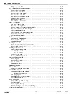
Page 65: ... Electrical Components Check 4 9 Horn Function Check 4 9 Seat and Seat Belt 4 9 Seat Backrest Angle Adjustment 4 10 Seat Weight Suspension Adjustment 4 10 Seat Headrest Adjustment 4 10 Seat Forward Backward Position Adjustment 4 10 Armrest Angle Adjustment 4 10 Seat Belt 4 11 Mirror Adjustment 4 11 Antenna Adjustment 4 11 Starting the Engine 4 12 Idling the Engine 4 13 Cold Weather Engine Starting...

Page 66: ...aveling at High Speed 4 23 Operating in Water 4 23 Traveling on an Incline 4 24 Precautions When Traveling on an Incline 4 24 Engine Stalls on an Incline 4 25 Operating on Soft Ground 4 26 Removing a Stuck Machine 4 26 One Track Stuck 4 26 Two Tracks Stuck 4 26 Towing the Machine 4 26 Towing Point for a Light Load 4 27 Recommended Operations 4 27 Trenching Work 4 27 Boom Swing Feature 4 27 Vehicle...

Page 67: ...MACHINE OPERATION 4 3 SY60C Excavator OMM Transportation Method 4 33 Loading and Unloading 4 33 Loading the Machine 4 33 Securing the Machine 4 35 Unloading the Machine 4 35 Lifting the Machine 4 36 ...

Page 68: ...neutral or low idle position and that the engine is shut down Give warning signals when necessary Seat Belt Usage Always wear the seat belt when operating the machine WARNING The seat belt is designed to protect the operator from danger especially when the machine is traveling Failure to wear a seat belt when operating the machine could result in death or serious injury Operation and Maintenance M...

Page 69: ...st the mirrors so the area behind the machine is visible from the operator seat See Mirror Adjustment on page 4 11 Check the seat belt and buckle for damage or wear See Seat Belt on page 4 11 Check the monitor in the cab Fluid Level Checks NOTE Complete the following procedures in this section before starting the engine Check Engine Coolant Level WARNING Engine coolant is toxic Avoid inhaling or i...

Page 70: ... environmental regulations Failure to do so could result in damage to the environment 1 Prepare the machine for maintenance See Maintenance Safety on page 2 5 2 Open the engine hood See Opening the Engine Hood on page 5 14 0002862 Figure 4 3 3 Remove the dipstick 1 and wipe the engine oil off with a clean cloth and install the dipstick 0002972 Figure 4 4 4 Remove the dipstick Make sure the oil lev...

Page 71: ...ill strainer 2 Fill the machine with fresh clean diesel fuel as necessary 3 Install the fuel filler cap after fueling Check and Drain the Fuel Water Separator WARNING Fuel or fuel vapors that come into contact with hot surfaces or electrical components can cause a fire that could result in death or serious injury Never service the fuel system near an open flame or while smoking Clean up spilled fu...

Page 72: ...3 0003006 Figure 4 9 4 Check the hydraulic oil level in the hydraulic oil tank through the sight gauge 1 The hydraulic oil level should be between the H 2 and L 3 marks 5 If the level is below the L mark add hydraulic oil See Add Hydraulic Oil on page 5 29 Check and Fill the Windshield Washer Fluid 1 Prepare the machine for service See Maintenance Safety on page 2 5 0002962 Figure 4 10 NOTE Keep d...

Page 73: ...battery cables and wires are clean and in good condition when inspecting the battery starting motor and alternator See Batteries on page 5 27 Clear the area around the battery of combustible materials For additional information about troubleshooting faults in the electrical system contact a SANY dealer Horn Function Check 1 Turn the key switch to ON 0002266 Figure 4 11 2 The horn sounds when the h...

Page 74: ...t lever 1 located below the front edge of the seat to adjust the seat suspension NOTE To achieve the best adjustment adjust the reading on the dial 2 to the weight of operator kg Seat Headrest Adjustment 0003049 Figure 4 15 The headrest 1 can be moved up or down to be positioned in line with the operator s head Seat Forward Backward Position Adjustment 0003043 Figure 4 16 When seated lift and hold...

Page 75: ... upward to lengthen the belt Insert the latch plate into the buckle 2 until it locks WARNING Keep belt slack to no more than 1 in 25 mm Belt slack beyond this amount could significantly reduce your protection in an accident Failure to follow this warning could result in death or serious injury 2 The belt should be placed as low as possible on your hips not on your waist Pull on the loose belt from...

Page 76: ...he Fuel Water Separator on page 4 7 2 Turn the battery disconnect switch to ON See Battery Disconnect Switch on page 3 21 3 When in the operator seat buckle the seat belt See Seat Belt on page 4 11 0002764 Figure 4 21 WARNING The machine should not move when the hydraulic lockout control lever is in the closed position If it does contact a SANY dealer Failure to correct this could result in death ...

Page 77: ...in the Fuel Water Separator on page 4 7 2 Turn the battery disconnect switch to ON See Battery Disconnect Switch on page 3 21 3 When in the operator seat buckle the seat belt See Seat Belt on page 4 11 WARNING The machine should not move when the hydraulic lockout control lever is in the closed position If it does contact a SANY dealer Failure to correct this could result in death or serious injur...

Page 78: ... In NOTE The machine has been thoroughly tested and adjusted before shipment However initial operation of the machine under severe conditions can adversely affect the performance of the new machine or shorten the machine life SANY recommends a break in period of 100 service hours for a new machine Properly breaking in a new machine is crucial for long service life by allowing time for internal eng...

Page 79: ... idle for 5 minutes to cool down 5 Turn the key switch to OFF and remove the key Inspection after Engine Shutdown 1 After shutting down the engine conduct a walk around inspection Check the work equipment the exterior of the machine and the undercarriage 2 Check for fluid leaks 3 Fill the fuel tank with diesel fuel 4 To prevent fires clear the engine compartment of combustible debris 5 Clean mud f...

Page 80: ...ing direction of the travel control lever pedal The machine will move forward when you pull the control levers backward and backward when you push the control levers forward Left and right control directions are also reversed when the track frame faces backward Travel Control NOTICE Stop the machine for 5 minutes after every 15 minutes of traveling Prolonged traveling may strain the travel motors ...

Page 81: ...urn the machine to the right Left Turn 0002830 Figure 4 31 Push the right travel control lever 1 or press the top of the right foot pedal 2 with the left travel control lever and foot pedal in the neutral position to turn the machine to the left Stopping the Machine 0002832 Figure 4 32 NOTICE Do not stop the machine suddenly except in an emergency Failure to follow this notice could result in mach...

Page 82: ... Figure 4 35 To raise the boom pull the right joystick To lower the boom push the right joystick Boom Control BHL Mode 0003060 Figure 4 36 To raise the boom pull the left joystick To lower the boom push the left joystick Bucket Control SAE BHL Mode 0002833 Figure 4 37 To uncurl the bucket move the right joystick to the right To curl the bucket move the right joystick to the left Swing Control SAE ...

Page 83: ... the machine is traveling When the engine auto idle is on moving any control lever increases the engine speed Avoid sudden stops when operating work equipment Hydraulic shock can damage the hydraulic system Avoid any working conditions that may cause the machine to tip over Avoid moving any control lever or pedal to abruptly change the direction of the machine Do not operate the machine on any gro...

Page 84: ... and may reduce the service life of the machine Never Use Traveling Force 0002865 Figure 4 44 Never use the machine s traveling force to cut the bucket into the ground to excavate Such an operation may damage the machine or the work equipment Do Not Operate a Cylinder to the Stroke End 0002849 Figure 4 45 Avoid operating the machine with any cylinder fully retracted or extended If the cylinder pis...

Page 85: ...dozer blade or the hydraulic cylinder Avoid Shifting Travel Directions Suddenly 0002873 Figure 4 48 Never shift the control levers quickly since it can lead to sudden unexpected travel Avoid moving the control levers quickly from forward travel to reverse travel Never move the control levers quickly from high speed to neutral Excavating Hard or Rocky Ground Use alternate work equipment to break up...

Page 86: ... 0002881 Figure 4 51 Never let the machine make contact with power lines or bridges 2 0002883 Figure 4 52 CAUTION Do not drive or swing the machine on broken stones rugged surfaces steel bars or scrap iron This could cause personal injury or track damage NOTICE Do not perform operations where the rubber tracks may skid This can cause early track wear 0002885 Figure 4 53 Slow the machine when trave...

Page 87: ...o operate improperly Do not drive the machine into water where the water depth is above the center of the final sprocket 1 Grease the parts that have been submerged until the old grease has been displaced from the bearing especially from the bucket pin Make sure that the job site surface is hard enough for the machine 0002889 Figure 4 55 Continuously monitor the condition of the machine when opera...

Page 88: ... grade greater than 30 Never attempt to cross a slope with a grade greater than 15 Always keep the seat belt fastened Keep the bucket pointed toward the traveling direction and 8 in 12 in 20 cm 30 cm off the ground Travel at low speed Do not attempt to change direction on a slope Only perform a direction change on an even and solid surface If the engine stalls on a slope lower the bucket to the gr...

Page 89: ...andarmuphillandkeepthebucket 8 in 12 in 20 cm 30 cm 7 off the ground Travel at a low speed 0002908 Figure 4 60 When traveling downhill keep the bucket in the traveling direction and 8 in 12 in 20 cm 30 cm 8 above the ground Lower the bucket immediately if the machine slips or loses balance Engine Stalls on an Incline If the engine stalls when the machine is on an incline lower the bucket to the gr...

Page 90: ...otating tracks are dangerous Stay away from rotating tracks Failure to follow this warning could result in death or serious injury 5 Remove mud buildup by operating the lifted track forward and backward 6 Place cribbing under the track to provide a firm surface if necessary 7 Raise the boom to lower the track onto the cribbing 8 Drive the machine out of the mud Two Tracks Stuck 1 Position the boom...

Page 91: ...commended Operations NOTICE Avoid sudden stops when lowering the boom Hydraulic shock can damage the hydraulic system Avoid extending the arm cylinder while in full travel This can damage the hydraulic cylinder Do not allow the bucket to come in contact with the tracks when excavating at an angle Do not allow the boom or arm hydraulic cylinder s hoses to come into contact with the ground Operate t...

Page 92: ...en operating the machine in narrow or confined spaces When loading a dump truck do not swing the bucket over the truck cab or any people on the job site Operate the machine on a hard level surface When working in a ditch or on a road shoulder keep the tracks perpendicular to the work face and the travel motors at the rear of the machine Placing the machine in this position helps facilitate escape ...

Page 93: ... disconnect switch to OFF 8 Close and lock all doors Parking the Machine on a Grade 0002928 Figure 4 71 WARNING Avoid parking the machine on a grade when possible Machine may become unstable and roll over Failure to follow this warning could result in death or serious injury If it is necessary to park the machine on a grade 1 Face the machine uphill 2 Firmly set the bucket teeth and dozer blade in...

Page 94: ... operation can fail if the machine becomes stuck After operating the machine in water or mud perform the following procedures to drain water from the undercarriage to extend its service life 1 Run the engine at low speed and swing the upper structure 90 so the work equipment is sideways WARNING Rotating tracks are dangerous Stay away from rotating tracks Failure to follow this warning could result...

Page 95: ...or serious injury During the storage period operate the machine on a monthly basis to prevent rust and seizing of moving parts and to lubricate the seals Charge the battery at this time Removing from Storage NOTICE If machine was not operated monthly contact a SANY dealer before using the machine Follow the procedures below before using a machine that has been stored for a prolonged period of time...

Page 96: ...he throttle control dial is at MIN low idle Starting with the throttle control dial at MAX high idle will accelerate the engine and could damage it 6 Adjust the throttle control dial 3 to MAX high idle for 3 seconds 7 Turn the throttle control dial to MIN low idle 0002756 Figure 4 4 8 Turn the key switch 4 to ON and check the monitor If all readings are normal and no fault codes are present the di...

Page 97: ...hazards Deactivate the auto idle mode before loading or unloading otherwise the machine may move suddenly Adjust the throttle control dial to MIN low idle Operating the engine at high speed could result in sudden unexpected movement Swinging the upper structure may cause the machine to tip over Grease mud or ice on the trailer loading platform and ramps can cause the machine to slide and tip over ...

Page 98: ...2944 Figure 4 9 NOTE To prevent damage to the bucket cylinder place a wood block 1 between the bucket cylinder and the trailer floor Slowly lower the bucket cylinder onto the wood block 0002940 Figure 4 10 6 When loading the excavator without equipment installed travel in reverse up the ramps Maintain the ramps at no more than a 15 angle 1 7 Stop the engine and turn key to ON 8 Operate the joystic...

Page 99: ... both ends of the tracks 2 Secure the machine firmly in place with chains or wire ropes to prevent it from sliding Unloading the Machine NOTICE Use extreme care when the machine drives over the joint area between the trailer and the ramps Position the boom and arm at an angle between 90 and 110 Do not unload the machine with the arm retracted Failure to follow these notices could result in damage ...

Page 100: ...ion and with sufficient capacity rating to safely support the intended load Never lift the machine with a person inside the cab Allow no one to stand close to or under a lifted machine Always lift with the longitudinal centerlines of the upper structure and undercarriage parallel to each other Keep the hydraulic lockout control lever in the locked closed position to prevent unexpected movement of ...

Page 101: ... disconnect switch to OFF 7 Lock all doors and hoods 8 Cover the exhaust opening to prevent contamination 0002956 Figure 4 18 0002971 Figure 4 19 9 Use wire ropes and a spreader bar 1 that have adequate length to prevent machine damage 10 Pass the wire ropes under the tracks as shown and anchor the ropes on the crane hook 11 Lift the machine 10 in 12 in 25 cm 30 cm and check its balance If it is n...

Page 102: ...4 38 MACHINE OPERATION SY60C Excavator OMM Page Intentionally Blank ...

Page 103: ...ronments 5 6 Cold Environments 5 6 Other Weather Environments 5 6 Check the Maintenance Log 5 6 Recommended Lubricants Fuel and Engine Coolant 5 7 Hydraulic Oil Description 5 7 Fuel 5 7 Lubrication and Grease 5 7 Engine Coolant 5 7 Windshield Washer Fluid 5 7 Engine Oil Viscosity Temperature Data 5 8 Fluid Capacities 5 8 Maintenance Schedule 5 9 Daily Maintenance and Inspection 5 9 When Required 5...

Page 104: ...eplace the Air Filters 5 20 Check the Dust Valve 5 20 Replace Air Filters 5 21 Check the Alternator 5 21 Check the Starter 5 21 Engine Cooling System 5 22 Change the Engine Coolant 5 22 Inspect and Clean the Cooling Package 5 23 Inspect the Engine Coolant Pump 5 23 Climate Control System 5 24 Service Intervals 5 24 Check and Adjust the Air Conditioner Compressor Belt Tension 5 24 Two Methods of Ch...

Page 105: ... Final Drive Motor Mounting Fasteners 5 38 Lubrication 5 39 Lubrication Points 5 39 Arm Cylinder Rod End Pin 5 39 Boom Arm Connecting Pin 5 40 Arm Cylinder Base End Pin 5 40 Boom Pin 5 40 Boom Swing Cylinder Base End Pin 5 40 Swing Gear 5 41 Swing Bearing 5 41 Boom Swing Pin 5 41 Dozer Blade Linkage Pins 5 41 Dozer Blade Cylinder End Pins 5 42 Boom Swing Cylinder Rod End Pin 5 42 Boom Cylinder Bas...

Page 106: ... daily basis Confirm hour meter readings with the required maintenance intervals listed in this manual See Home Screen on page 3 5 Genuine SANY Parts Use genuine SANY replacement parts when repairing or replacing machine components Failure to do so may result in premature system or part failure SANY Approved Lubricants Always use SANY approved lubricants and engine coolants Never mix different lub...

Page 107: ...t pins Failure to disconnect the negative battery cable could result in damage to the machine or cause the machine to operate improperly Daily Inspection and Maintenance Before operation check the following with the engine off Check the engine oil level See page 4 6 Check the hydraulic oil level See page 5 29 Check the coolant level See page 4 5 Drain the water and sediment in the fuel tank and wa...

Page 108: ...tly to prevent blockage Fuel equipment Drain sediment frequently Fresh air and recirculation filters Clean the filters frequently Cold Environments In extremely cold environments 32 F 0 C or below use only the fuels lubricants and engine coolants listed in Recommended Lubricants Fuel and Engine Coolant on page 5 7 Engine coolant is an important fluid protecting against engine freezing and coolant ...

Page 109: ...l fuel In cold weather climates use a mixture of 2 diesel and 1 diesel fuels Use only ultra low sulfur fuel with a limit of S 15 mg kg for all normal operations SANY does not recommend the use of any diesel fuel with a Cetane level less than 40 Do not use gasoline kerosene or any unapproved fuels in the fuel system If fuel waxing or bacterial growth occurs in the fuel system contact a SANY dealer ...

Page 110: ...stem Oil Type Ambient Temperature 22 F 30 C 4 F 20 C 14 F 10 C 32 F 0 C 50 F 10 C 68 F 20 C 86 F 30 C 104 F 40 C 122 F 50 C Engine Engine oil SAE 30 SAE 10W SAE 10W 30 SAE 15W 40 Swing machinery case Gear oil SAE 30 Track roller SAE 30 Idler SAE 30 Final drive SAE 30 Carrier roller SAE 30 Hydraulic system Hydraulic oil SAE 10W SAE 10W 30 SAE 15W 40 ISO VG32 ISO VG46 ISO VG68 Fuel tank Diesel fuel ...

Page 111: ...the bucket See page 5 46 Check the air filter if a restriction warning is displayed See page 5 20 After the First 50 Hours Initial change of the engine oil and filter See page 5 19 Weekly or Every 50 Hours Lubricate the bucket linkage pins See page 5 43 Check the batteries See page 5 27 Check the hydraulic hoses lines and connectors See page 5 34 Check the final drive oil level See page 5 36 Check...

Page 112: ...ne valve clearance Contact a SANY dealer for more information Change the hydraulic oil See page 5 33 Change the engine coolant See page 5 22 Change the final drive oil See page 5 37 Hydraulic Breaker Maintenance Interval Hydraulic oil breaks down faster on machines equipped with a hydraulic breaker than on machines equipped with a bucket Change the hydraulic oil and filters every 400 hours on brea...

Page 113: ...e that has escaped Shown below are the lubrication points that must be maintained according to the lubrication chart See Lubrication Points on page 5 39 0002197 Figure 5 1 Lubrication Chart Item Maintenance Items Qty of Fittings Lubrication Interval Lubricant Daily 100 hr 250 hr 500 hr 1 Arm cylinder pins 2 Grease 2 Boom arm connecting pin 1 3 Boom pin 1 4 Boom swing cylinder base end 1 5 Swing ge...

Page 114: ...lacement on a new machine Clean or drain as applicable Replacement Item Intervals Replacement Items When Required 8 hr 50 hr 100 hr 250 hr 500 hr 1000 hr 2000 hr Engine oil and filter Engine coolant Fuel water separator element Fuel filter Primary air filter Secondary air filter Hydraulic suction strainer Hydraulic return filter Hydraulic tank breather filter element Hydraulic pilot filter Hydraul...

Page 115: ...e push down on the release lever 6 located on the left side of the operator seat Left and Right Rear Access Doors 0003211 Figure 5 4 The left 1 and right 3 rear access doors are opened after the engine hood 2 is opened NOTE The left and right rear access doors must be closed before the engine hood is closed The left and right rear access doors are secured closed by the engine hood See Closing the ...

Page 116: ... turn to the counterclockwise position to unlock the hood 0002856 Figure 5 9 2 Pull outward on the latch 3 and open the engine hood 1 NOTE The hood is supported by two pneumatic cylinders 4 Closing the Engine Hood NOTE Before closing the hood make sure the right and left access doors are closed 1 Close the engine hood Make sure the right and left access doors are closed and the hood is firmly seat...

Page 117: ...the way into the lock The key may break if it is turned before it is fully inserted 3 Turn the key from position 3 clockwise until the key slot points to position 4 and remove the filler cap Position 4 Unlocked Position 3 Locked Closing the Fuel Tank Filler Cap 0002825 Figure 5 12 1 Install the filler cap 2 onto the filler tube 2 Insert the key into the key slot 3 Turn the key from position 4 coun...

Page 118: ...ifting up the adjacent corner of the cover Repeat for the other three tabs to release the cover Fuse Replacement 0002857 Figure 5 16 1 Use the fuse removal and installation tool 1 to pull a blown fuse and install a new fuse 2 Spare fuses 2 can be used for replacing a blown fuse Always replace a fuse with a fuse of the same amperage rating Fuse Circuits 1 2 3 4 4 Fuse Amperage Circuit F1 25 Amp Sta...

Page 119: ...leshooting electrical problems with the machine Relay Amperage Circuit K3 12V 35 Amp Starting K5 12V 35 Amp Horn K6 12V 35 Amp Work lights K7 12V 35 Amp Cold weather starting K8 12V 35 Amp Monitor power down K9 12V 35 Amp Spare K12 12V 35 Amp HVAC system fan K13 12V 35 Amp A C compressor ...

Page 120: ...l problems and prevent defects that may lead to service interruption and costly repair 1 Prepare the machine for service See Maintenance Safety on page 2 5 2 Shut the engine off Open the engine hood and left and right access doors 3 Inspect the engine and engine compartment for Oil fuel and coolant leaks Loose fasteners and connections Worn or loose belts Damaged hoses and wiring harnesses Prestar...

Page 121: ...g gasket 8 Install the new oil filter by hand until the oil filter O ring touches the oil filter housing Tighten the oil filter 3 4 to 1 full turn by hand to securely install the oil filter NOTE Overtightening the filter may damage the O ring resulting in an oil leak 9 Remove the fill cap and add engine oil until the level is at the upper mark on the dipstick See Check Engine Oil Level on page 4 6...

Page 122: ...ener 6 and tension adjuster locknut 7 4 Turn the tension adjuster 4 to achieve the specified belt tension 5 Tighten the adjusting plate fastener alternator bracket fastener and tension adjuster locknut 6 Check the fan belt tension to confirm adjustment Replace the Fan Belt Visually inspect the condition of the fan belt Belts that have been exposed to oil or engine coolant or show signs of damage o...

Page 123: ...ont access door and locate the air filter housing 3 Release the three latches 2 and remove the end cover 0002896 Figure 5 23 NOTE Clean the interior of the housing before removing the primary filter element 4 Remove the primary filter element 5 and then the secondary filter element 4 5 Installation is in the reverse order of removal Check the Alternator Prepare the machine for service See Maintena...

Page 124: ...Figure 5 24 2 Slowly loosen and remove the radiator cap 1 0002898 Figure 5 25 NOTE For engine cooling system capacity see Fluid Capacities on page 5 8 3 Follow the drain hose 3 from the drain valve 2 to where it exits the bottom of the machine Place an appropriate container under the drain hose Open the drain valve and allow the engine coolant to drain 4 Close the drain valve Add clean water to fi...

Page 125: ... fins may lead to leaks and overheating In dusty environments inspect the cooling fins daily regardless of the maintenance schedule 1 Prepare the machine for service See Maintenance Safety on page 2 5 0002957 Figure 5 27 2 Open the engine hood 1 and the right rear access door 4 NOTE Maintain a minimum distance of 12 in 30 cm from the cooling fins during cleaning 3 Check the front and rear of the r...

Page 126: ...ICE Check the pulleys and V belt for damage and wear Make sure that the V belt does not rub against the bottom groove of the pulleys A newly installed V belt must be readjusted after operating the machine for 1 hour 0002958 Figure 5 30 1 Prepare the machine for service See Maintenance Safety on page 2 5 2 Loosen the belt adjustment pulley locknut 1 and turn the tension adjuster 2 to achieve the co...

Page 127: ...e Fuel System NOTE Air trapped in the fuel system may cause engine starting failure or abnormal running After servicing the fuel system or running out of fuel the key switch should be turned to ON for 2 to 3 minutes before attempting to start the engine The lift pump will bleed air from the system Drain the Fuel Tank WARNING Fuel or fuel vapors that come into contact with hot surfaces or electrica...

Page 128: ...al regulations Failure to do so could result in damage to the environment 1 Prepare the machine for service See Maintenance Safety on page 2 5 0002960 Figure 5 34 2 Place a container under the fuel filter 1 to collect any spilled fuel 3 Remove the fuel filter with a filter wrench NOTE Always use SANY approved fuel filters 4 Clean the mounting base of the fuel filter and fill the new fuel filter wi...

Page 129: ...RNING Before proceeding with any battery maintenance procedure observe the following The top of the battery must be kept clean to prevent plugging of the battery vents Regularly wash the top of the battery to prevent the battery vents from plugging Battery gases are explosive Never smoke around batteries or expose them to sparks or open flames Work in a well ventilated area Wear personal protectiv...

Page 130: ...fresh water and seek medical attention Failure to follow these warnings could result in death or serious injury NOTICE After machine shutdown wait at least 1 minute for the Engine Control Module ECM to complete its shutdown before disconnecting the batteries Failure to observe and follow this notice can cause damage to the machine or cause the machine to operate improperly 1 Prepare the machine fo...

Page 131: ...en position 6 Use the joystick control to lower the boom 7 The boom should lower NOTE If there is no movement contact a SANY dealer Relieve Hydraulic System Pressure NOTE Hydraulic system pressure must be relieved before disconnecting or servicing hydraulic system components 1 Prepare the machine for service See Maintenance Safety on page 2 5 2 Turn the key switch to ON Do not start the engine 3 S...

Page 132: ...Check Hydraulic Oil Level on page 4 8 7 Install the hydraulic oil return filter cover See Replace the Hydraulic Oil Return Filter on page 5 31 8 Install the top access panel and intake cover Replace the Hydraulic Tank Breather Filter Element WARNING Allow the hydraulic system to cool before servicing Hot oil may cause burns or other serious injury The hydraulic tank may be under pressure and hydra...

Page 133: ...from the housing Use a lint free cloth to clean the interior of the housing and bowl NOTE Always use SANY approved oil filters 6 Install a new filter element gasket and O ring 7 Install the filter bowl and tighten securely 8 To purge air from the system start the engine and run at low idle for 10 minutes 9 Check the hydraulic oil level and add hydraulic oil as needed See Check Hydraulic Oil Level ...

Page 134: ...filter and spring Install a new return filter and spring 8 Install a new O ring for the return filter cover Tighten the fasteners securely 9 To purge air from the system start the engine and run at low idle for 10 minutes 10 Check the hydraulic oil level and add hydraulic oil as needed See Check Hydraulic Oil Level on page 4 8 Clean and Replace the Hydraulic Oil Suction Strainer WARNING Allow the ...

Page 135: ...y be present at the filter cover Relieve any pressure to prevent injury Failure to follow these warnings could result in death or serious injury 1 Obtain an oil analysis sample kit from a SANY dealer 2 Operate the machine until the hydraulic oil is up to normal operating temperature 3 Prepare the machine for service See Maintenance Safety on page 2 5 NOTICE It is critical that all material used to...

Page 136: ...e 5 48 4 Remove the four fasteners 1 securing the center lower access panel 2 Remove the access panel 0003010 Figure 5 49 NOTE For hydraulic tank capacity see Fluid Capacities on page 5 8 5 Place a suitable container under the drain plug 3 Remove the drain plug and allow the oil to drain 6 Install the drain plug and the center lower access panel 7 Fill the hydraulic tank to the specified level See...

Page 137: ...alve Failure to follow these warnings could result in death or serious injury WARNING If the track remains too tight after opening the track tension grease valve or if the track remains too loose after adding grease to the track tension grease fitting do not attempt to remove the track or remove the track adjuster If this occurs contact a SANY dealer for further instructions Pressurized grease ins...

Page 138: ...e fasteners Check and Add Final Drive Oil CAUTION Allow the final drive to cool before servicing Hot oil may cause burns or other serious injury Wear safety goggles gloves and other personal protective equipment PPE to prevent serious injury The final drive oil may be under pressure Remove the plugs slowly to prevent injury Failure to follow these precautions could result in injury 0003040 Figure ...

Page 139: ...es on page 5 8 6 Remove the drain plug and allow the oil to drain 7 Install the drain plug and tighten to 12 5 lb ft 17 N m 8 Add new gear oil through the fill plug opening Fill until the gear oil is at the lower edge of the level plug opening 9 Install the oil level and fill plugs and tighten to 12 5 lb ft 17 N m 10 Repeat this procedure on the other final drive Collect Final Drive Oil Sample CAU...

Page 140: ...ew fasteners 5 Replace any damaged or defective fasteners and tighten any loose fasteners Final drive mounting fasteners are tightened to 117 lb ft 144 lb ft 158 N m 196 N m 6 Install the travel motor cover 2 and secure with fasteners 1 The travel motor cover fasteners are tightened to 33 lb ft 43 lb ft 45 N m 59 N m 0003040 Figure 5 3 7 Inspect the sprocket mounting bolts 4 on the opposite side o...

Page 141: ...e 2 5 2 Using a grease gun pump grease into the grease fittings 3 Clean off all excess grease Arm Cylinder Rod End Pin 0003021 Figure 5 5 1 Remove the grease fitting cap 1 from the arm cylinder rod end pin grease fitting 2 1 Arm cylinder rod end pin page 5 39 9 Dozer blade linkage pins page 5 41 2 Boom arm connecting pin page 5 40 10 Dozer blade cylinder end pins page 5 42 3 Arm cylinder base end ...

Page 142: ...tting cap 1 from the arm cylinder base end pin grease fitting 2 2 Grease the arm cylinder base end pin grease fitting 3 Wipe excess grease from around the grease fitting 4 Install the grease fitting cap Boom Pin 0003024 Figure 5 8 1 Remove the grease fitting cap 1 from the boom pin grease fitting 2 2 Grease the boom pin grease fitting 3 Wipe excess grease from around the grease fitting 4 Install t...

Page 143: ...ut down the machine 4 Repeat steps 1 through 3 until grease appears from the swing bearing seal NOTE Wipe excess grease from around the grease fittings Boom Swing Pin 0003028 Figure 5 12 1 Remove the grease fitting cap 1 from the grease the boom swing pin fitting 2 2 Grease the boom swing pin fitting NOTE Wipe excess grease from around the grease fitting 3 Install the grease fitting cap Dozer Blad...

Page 144: ... Grease the boom swing cylinder rod end pin fitting NOTE Wipe excess grease from around the grease fitting 3 Install the grease fitting cap Boom Cylinder Base End Pin 0003031 Figure 5 16 1 Remove the grease fitting cap 1 from the boom cylinder base end pin grease fitting 2 2 Grease the boom cylinder base end pin grease fitting NOTE Wipe excess grease from around the grease fitting 3 Install the gr...

Page 145: ...19 1 Remove the grease fitting caps 1 from the bucket cylinder rod end pin grease fittings 2 2 Grease the bucket cylinder rod end pin grease fittings NOTE Wipe excess grease from around the grease fittings 3 Install the grease fitting caps Bucket Cylinder Base End Pin 0003034 Figure 5 20 1 Remove the grease fitting cap 1 from the bucket cylinder base end pin grease fitting 2 2 Grease the bucket cy...

Page 146: ...each side Inspect and Lubricate the Cab Door Hinges and Front Window Slide Rail 0002969 Figure 5 24 Grease the two cab door hinges 1 until grease comes out of the hinge 0002970 Figure 5 25 Apply a lubricating silicone to the slide rails 2 on both sides of the cab door ceiling Inspect and Tighten the Windshield Wiper Arm Nut 0002963 Figure 5 26 Raise the nut cap 1 at the end of the wiper arm and ch...

Page 147: ...gs could result in death or serious injury NOTE Bucket teeth must be replaced before the bucket tooth adapter wears out 1 Prepare the machine for service See Maintenance Safety on page 2 5 0002349 Figure 5 27 2 Measure the length of the bucket teeth 1 If the bucket teeth are worn more than the service limit dimension 2 replace the bucket teeth The dimension of new bucket teeth is 5 90 in 150 mm Th...

Page 148: ...ine for service See Maintenance Safety on page 2 5 0002279 Figure 5 31 2 Lower the bucket to the ground and support the bucket to prevent it from rolling over when the bucket pin is removed 0002354 Figure 5 32 3 Remove the bucket pin hardware and bucket pins 1 and 2 and remove the bucket 3 from the arm 4 and linkage 5 4 Clean the pins and pin bores Lubricate the pin bores with grease 5 Align the a...

Page 149: ...6 1 SY60C Excavator OMM Specifications Machine Dimensions 6 2 Working Range 6 3 Technical Specifications 6 4 Lift Chart Blade Down 6 5 Lift Chart Blade Up 6 6 Chapter 6 ...

Page 150: ...n 6015 mm 3 Tail swing radius 5 ft 5 in 1640 mm 4 Dozer blade height 1 ft 1 in 340 mm 5 Track length on ground 6 ft 9 in 2045 mm 6 Track length 8 ft 4 in 2545 mm 7 Transport height 8 ft 8 in 2645 mm 8 Standard track width 1 ft 4 in 400 mm 9 Minimum ground clearance 1 ft 1 in 330 mm 10 Track gauge 5 ft 3 in 1600 mm 11 Transport width 6 ft 7 in 2005 mm 2 5 3 6 1 7 10 11 4 9 8 ...

Page 151: ...dius 14 ft 8 76 in 4 49 m 3 Maximum dumping height 13 ft 4 in 4 06 m 4 Minimum swing radius 8 ft 5 in 2 55 m 5 Maximum dozer raising height 1 ft 3 12 in 385 mm 6 Maximum dozer lowering depth 1 ft 2 88 in 380 mm 7 Maximum reach at ground level 20 ft 8 76 in 6 32 m 8 Maximum vertical wall digging depth 10 ft 5 16 in 3 18 m 9 Maximum digging depth 13 ft 3 95 m 9 8 1 3 4 5 7 6 2 ...

Page 152: ...MPa Travel motor Axial piston with park brake Travel pressure maximum 3553 psi 24 5 MPa Travel speed high low high speed 2 4 mph 3 7 km h low speed 1 5 mph 2 40 km h Travel effort maximum 10 611 lbf 47 2 kN Grade capability maximum 35 Swing motor Axial piston with swing brake Swing pressure maximum 2770 psi 19 1 MPa Swing speed 9 6 rpm Undercarriage standard Belted rubber track Track shoe width st...

Page 153: ...g Load Point Radius ft m 6 6 2 0 9 8 3 0 13 1 4 0 16 4 5 0 Lift capacity at max reach End Side End Side End Side End Side End Side 13 1 4 0 2205 1000 2205 1000 2425 1100 1874 850 9 8 3 0 2535 1150 2205 1000 2425 1100 1433 650 2535 1150 1433 650 6 6 2 0 3968 1800 3086 1400 2976 1350 2094 950 2646 1200 1433 650 2646 1200 1323 600 3 3 1 0 5401 2450 2756 1250 3638 1650 1874 850 2976 1350 1433 650 2756...

Page 154: ...b kg Load Point Radius ft m 6 6 2 0 9 8 3 0 13 1 4 0 16 4 5 0 Lift capacity at max reach End Side End Side End Side End Side End Side 13 1 4 0 2205 1000 2205 1000 2205 1000 1874 850 9 8 3 0 2205 1000 2205 1000 1984 900 1433 650 1984 900 1433 650 6 6 2 0 3968 1800 3086 1400 2866 1300 2094 950 1984 900 1433 650 1764 800 1323 600 3 3 1 0 3968 1800 2756 1250 2646 1200 1874 850 1984 900 1433 650 1764 8...

Page 155: ...M Optional Equipment Optional Equipment Selection 7 2 Read Equipment Instructions 7 2 Removal and Installation Precautions 7 2 Operation Precautions 7 2 Install Optional Equipment 7 3 Remove Optional Equipment 7 4 Chapter 7 ...

Page 156: ...manual and in the optional equipment manual Remove and install equipment only on a firm level surface Use an appropriate lifting device when handling heavy objects weighing more than 55 lb 25 kg Never stand under a suspended load Make sure the machine is well balanced and supported whenever installing or removing optional equipment For additional information about removal and installation of optio...

Page 157: ...n to catch any residual hydraulic oil 4 Remove the line nut 1 and plug 2 from the hydraulic line NOTE Right side shown Repeat for the left side 5 Connect the optional equipment to the machine in accordance with the manufacturer s instructions 6 Connect the optional equipment hydraulic lines and bleed the hydraulic system in accordance with the manufacturer s instructions 0003207 Figure 7 2 7 Adjus...

Page 158: ...e on page 5 29 NOTICE Dispose of the hydraulic oil in accordance with local environmental regulations Failure to do so could result in damage to the environment 3 Place a suitably sized container under the hydraulic connection to catch any residual hydraulic oil 4 Disconnect the optional equipment hydraulic lines in accordance with the manufacturer s instructions 0004528 Figure 7 3 5 Install the l...

Page 159: ...Page Intentionally Blank ...

Page 160: ...ice sanyamerica com SANY Part Number SSY005078669 318 Cooper Circle Peachtree City Georgia 30269 Fax 770 632 7820 Sales E mail sales sanyamerica com Service E mail service sanyamerica com Service Hotline 470 552 SANY 7269 ...

Reviews: