-
9
-
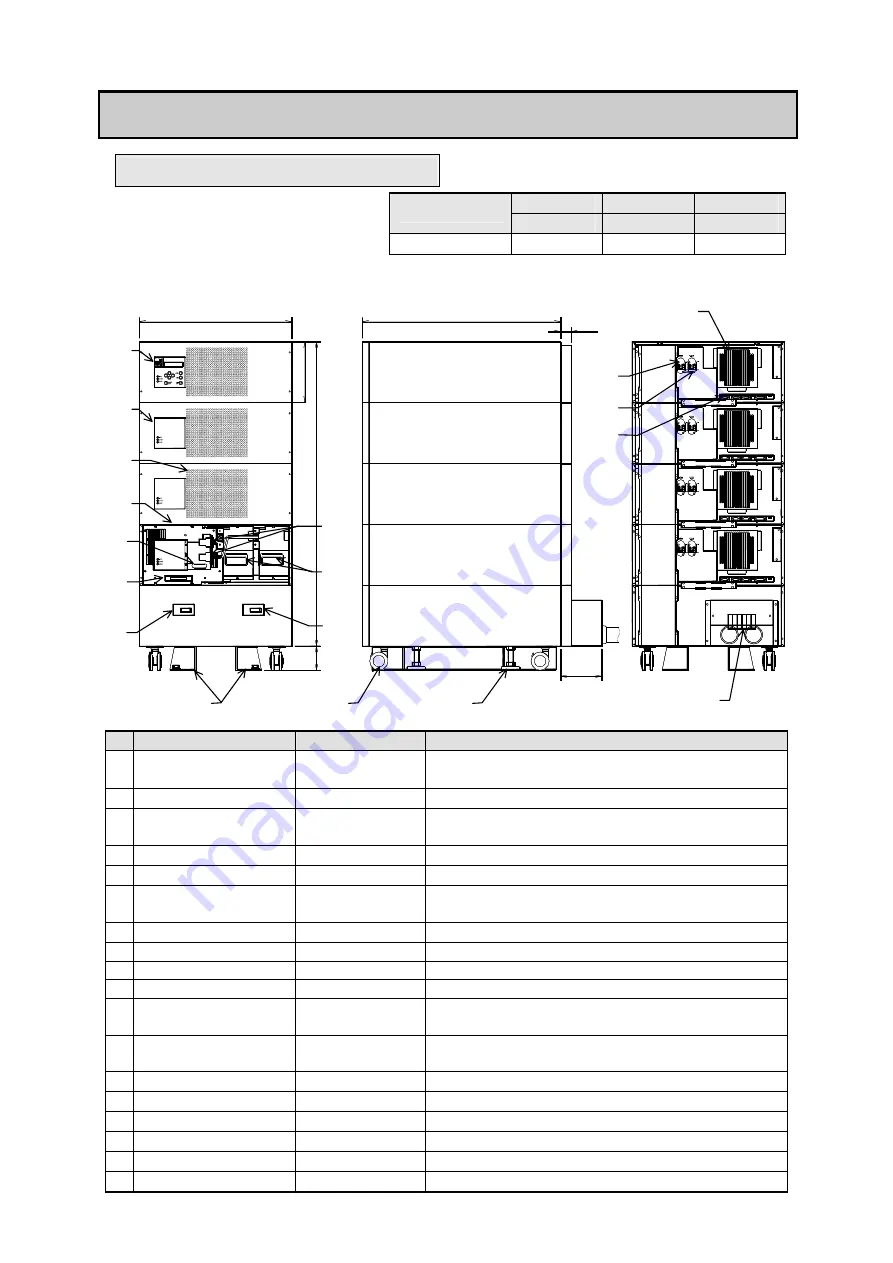
5. Outside dimensions and part names
5.1 Equipment
ASD70S2U
ASD100S2U
ASD140S2U
Type
ASD35S2NU
ASD70S2NU ASD100S2NU
The fig. below is ASD140S2U.
Number of units is different in each type.
Dimension "H" is shown in a right table.
Dimension H(mm)
600
800
1000
Front Right side Back
No
Name
Display
Function
①
LCD panel
-
Displays the UPS status and measuremenes
.
Operate and set adout UPS.
②
LED panel
-
Display unit status.
③
Inverter module
-
Consists of rectifier, charger, inverter and bypass
circuit.
④
Battery module
-
Battery for back up for 10 minutes.
⑤
Battery connector
-
Used for connecting battery modules.
⑥
Auxiliary switch
-
Used for operation at emergency and setting unit
number.
⑦
Knob for pull
-
Used to pull out inverter module.
⑧
Main breaker
MAIN MCCB Input circuit protection.
⑨
Bypass breaker
BAYPASS MCCB Bypass ciucuit protection.
⑩
Output breaker
OUTPUT MCCB Output circuit protection.
⑪
Maintenance bypass
breaker
MAINTENANCE
BYPASS
To bypass UPS units during maintenance.
⑫
Input/Output
terminal block
L, N, U, V, G
Used for connection with Input, Output and
Ground.
⑬
Outside interface
-
Used for connection of external transmission signal.
⑭
Intake hole
-
Used for cooling.
⑮
Exhaust hole
-
Used for cooling.
⑯
Caster
-
Used to move.
⑰
Level adjuster
-
Used for fixation to the floor.
⑱
Floor fixed fitting
-
Used for fixation to the floor. (Option)
N
V U G
L G
ASD
H
650
80
500
135
35
20
0
⑧
⑥
⑨
⑩
⑤
⑱
③
⑮
⑬
⑦
⑫
②
①
④
⑰
⑯
⑭
⑪


