background image

3-phase STEPPING SYSTEMS

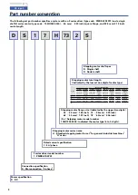
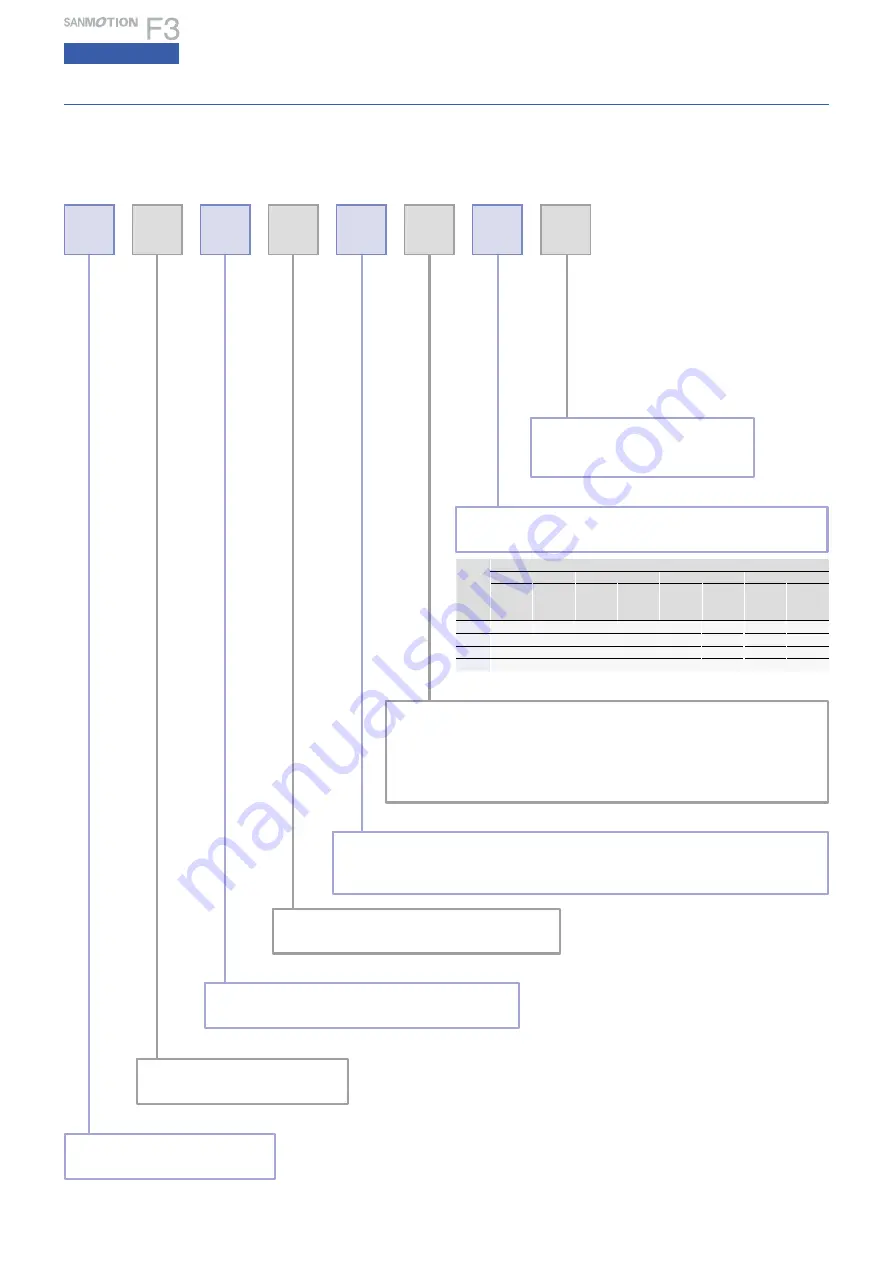
Part number convention

The following set part number specifies a system with an F series driver

type code : PMDSA1S3P01

and a single 

shaft H series motor

type code : 103H7332-0340

56 mm

2.20 inch

square flange, and 53.8 mm

2.12 inch

motor length.

D

1

7

H 73

Power specification

D

DC

F series driver model number

1

PMDSA1S3P01

Rated current specification

7 : 3 A/phase

Stepping motor series name

H : Standard stepping motor for set 

for general industrial machines


H

 series

Stepping motor flange size 

indicated by the upper two digits

  53

42 mm

1.65 inch

    73

56 mm

2.20 inch

  63

50 mm

1.97 inch

    78

60 mm

2.36 inch

Ex.

 Setpping motor model number 

103H7332-0340 : Indicated the motor type 

4 to 5 digits

.

2

S

S

DC input

Stepping motor total length

indicated by the lowest one digit of motor type

Stepping motor shaft spec

S : Single shaft

D : Double shaft

Connection specification

S : Star connection

3-phase

Code

Motor flange size

42 mm 

1.65 inch

50 mm

1.97 inch

56 mm

2.20 inch

60 mm

2.36 inch

Type code

Motor 

length 

: mm

inch

Type code

Motor 

length 

: mm

inch

Type code

Motor 

length 

: mm

inch

Type code

Motor 

length 

: mm

inch

1

2

5332

39

1.54

6332

51.3

2.02

7332

53.8

2.12

7832

53.8

2.12

3

5333

48

1.89

6333

64.8

2.55

7333

85.8

3.38

7833

85.8

3.38

4

Summary of Contents for Sanmotion F3

Page 1: ...3 PHASE STEPPING SYSTEMS Ver 2 ...

Page 2: ...1 B Stepping motor extension cable for 42 mm 1 65 inch 1m 3 28 feet UL1430AWG22 300V 105 C 1 3 1 3 B Stepping motor extension cable for 50 mm 1 97 inch 1m 3 28 feet UL1430AWG22 300V 105 C 8 1 C I O signal cable Pin number Color 1 Blue 2 3 4 5 6 7 8 9 10 11 Driver side Ranges of 3 phase stepping motors Compliance with international standards The standard specification SANMOTION F series stepping dri...

Page 3: ...tor Switches driver power on off Use together with a surge protector DC 24 V D Connector sets Model Used for Contents of set Quantity Manufacturer Applicable wire size Crimp tool number PM AP 036 DC source CN2 Applicable housing VHR 2N 1 J S TMfg Co Ltd AWG18 to 22 YC 160R Applicable contact SVH 21T P1 1 2 PM AP 041 42 mm 1 65 inch Stepping motor CN3 Applicable contact SVH 21T P1 1 1 J S TMfg Co L...

Page 4: ...r two digits 53 42 mm 1 65 inch 73 56 mm 2 20 inch 63 50 mm 1 97 inch 78 60 mm 2 36 inch Ex Setpping motor model number 103H7332 0340 Indicated the motor type 4 to 5 digits 2 S S DC input Stepping motor total length indicated by the lowest one digit of motor type Stepping motor shaft spec S Single shaft D Double shaft Connection specification S Star connection 3 phase Code Motor flange size 42 mm ...

Page 5: ...onservation temperature 20 to 70 C Operating ambient humidity 35 to 85 RH no condensation Conservation humidity 10 to 90 RH no condensation Vibration resistance 0 5G Tested under the following conditions frequency range 10 to 55 Hz direction along the X Y and Z axes for 2 hours Impact resistance Considering the NDS C 0110 standard section 3 2 2 division C not influenced Withstand voltage Not influen...

Page 6: ...10 2 25 Allowable radial load Note1 N lbs 26 5 85 25 5 62 Note1 When load is applied at 1 3 length from output shaft edge Note1 When load is applied at 1 3 length from output shaft edge Torque kgf cm Source current A Torque N m Pulse rate kpulse s Number of rotations min 1 1 division 2 division 0 1 1 10 100 0 1 2 3 4 5 6 7 8 9 10 2000 3000 5000 100 1000 2000 3000 5000 100 1000 10 1 2 3 4 5 0 0 1 0...

Page 7: ... A Torque N m Pulse rate kpulse s Number of rotations min 1 1 division 2 division 0 1 1 10 100 0 1 2 3 4 5 6 7 8 9 10 2000 3000 5000 100 1000 2000 3000 5000 100 1000 10 2 4 6 8 10 0 0 2 0 4 0 6 0 8 1 0 fs fs 120 100 80 60 40 20 140 0 Torque oz in Torque kgf cm Source current A Torque N m Pulse rate kpulse s Number of rotations min 1 1 division 2 division 0 1 1 10 100 0 1 2 3 4 5 6 7 8 9 10 2000 30...

Page 8: ...ion Function selection DIP switchpack Operation connection and function SL Automatic current reduction ON 100 of current rating when stopped OFF Approx 50 of current rating when stopped The factory settings are shown in the figure above Before changing the settings of the function selection DIP switches turn off the source of the PM driver Note 1 The temperature increase in the motor driver can be ...

Page 9: ... When the crest value of the input signal is 5 V the external limit resistance R must be 0 Ω When the crest value of the input signal exceeds 5 V use the external limit resistance R to limit the input current to approximately 15 mA 330 PM driver photo coupler Approx 15 mA 5 V Input signal R 5 6 Input circuit configuration power down input When the crest value of the input signal is 5 V the externa...

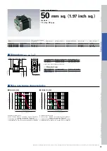
Page 10: ...8x10 4kg m2 4 37oz in2 use the direct coupling 103H5333 0340 Torque kgf cm Torque N m 0 1 1 10 100 Pulse rate kpulse s 2000 3000 5000 100 1000 Number of rotations min 1 0 1 0 2 0 3 0 4 0 5 0 1 2 3 4 5 0 Starting torque at JL2 Pull out torque at JL1 60 50 40 30 20 10 70 0 Torque oz in Model Holding torque at 2 phase energization Rated current Wiring resistance Winding inductance Rotor inertia Mass ...

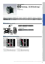
Page 11: ...8 10 0 Pull out torque at JL1 Starting torque at JL2 120 100 80 60 40 20 140 0 Torque oz in Model Holding torque at 2 phase energization Rated current Wiring resistance Winding inductance Rotor inertia Mass Weight Single shaft Double shafts N m oz in MIN A phase Ω phase mH phase 10 4 kg m2 oz in2 kg Ibs 103H6332 0340 0310 0 44 62 31 3 1 3 1 6 0 12 0 66 0 5 1 10 103H6333 0340 0310 0 58 82 13 3 1 6 ...

Page 12: ...10 100 Pulse rate kpulse s 2000 3000 5000 100 1000 Number of rotations min 1 0 4 0 8 1 2 1 6 2 0 4 8 12 16 20 0 Starting torque at JL2 Pull out torque at JL1 250 200 150 100 50 0 Torque oz in Model Holding torque at 2 phase energization Rated current Wiring resistance Winding inductance Rotor inertia Mass Weight Single shaft Double shafts N m oz in MIN A phase Ω phase mH phase 10 4 kg m2 oz in2 kg...

Page 13: ...7833 0340 Torque kgf cm Torque N m 0 1 1 10 100 Pulse rate kpulse s 2000 3000 5000 100 1000 Number of rotations min 1 0 4 0 8 1 2 1 6 2 0 4 8 12 16 20 0 Starting torque at JL2 Pull out torque at JL1 250 200 150 100 50 0 Torque oz in Model Holding torque at 2 phase energization Rated current Wiring resistance Winding inductance Rotor inertia Mass Weight Single shaft Double shafts N m oz in MIN A ph...

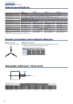
Page 14: ...025 mm 0 001 inch MAX Load 4 4N 1lbs Shaft runout 0 025 mm 0 001 inch Concentricity of mounting spigot relative to shaft Φ 0 05 mm 0 002 inch Φ 0 075 mm 0 003 inch Φ 0 075 mm 0 003 inch Φ 0 075 mm 0 003 inch Perpendicularity of mounting surface relative to shaft 0 1 mm 0 004 inch 0 1 mm 0 004 inch 0 075 mm 0 003 inch 0 075 mm 0 003 inch General specifications Note1 When load is applied at 1 3 leng...

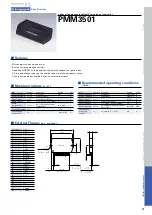
Page 15: ...rd temperature during operation TC MAX No condensation at low temperature 0 to 105 C Joint temperature Tj MAX 150 C Conservation temperature Tstg 40 to 125 C Item Symbol Condition Rating Unit Source voltage 1 VCC1 With signal 24 10 V Source voltage 2 VCC2 With signal 5 0 5 V Input voltage VIH 0 to VCC2 V Phase current 1 IO1 Without heat sink 1 7 A Phase current 2 IO2 TC 105 C Clock 100Hz 4 4 A Clo...

Page 16: ...ase x 0 41 Notice that 100Ω is recommended for R2 due to the configuration of the internal circuit of the PMM3501 Place the GND side of the source by pass capacitor of VCC1 C1 as close to pins 27 and 28 as possible to reduce noise Set RESET to High 10μsecs after 5 V rises above 4 5 V as shown in Fig 1 When turning on the power with ENABLE set to Low set RESET to High after 24 V rises completely Fu...

Page 17: ... handling the product After reading the Operation Manual or the like keep it in the place where the users can refer to whenever necessary This label is stuck near the high voltage part such as the electrically charged or cover protected section warning that the place where it is likely to cause an electric shock This label is stuck on the place where the driver or stepping motor body should be eas...

Page 18: ...Doing so may cause injury or fire 2 Have a person with expert knowledge for performing the transportation placement wiring operation maintenance or inspection of the product Without such knowledge it may cause an electric shock injury or fire 3 Do not work for wiring maintenance servicing or inspection with the electric power on Perform either of those five minutes after turning the power off or o...

Page 19: ...force in axial direction N Fb ball screw preload N T roll pushing force N Dr1 drive side roll diameter mm Dr2 follower side roll diameter mm Lr1 drive side roll length mm Lr2 follower side roll length mm G reduction ratio JG speed reducer inertia kg m2 JC coupling inertia kg m2 JN nut inertia kg m2 JO other motor axis conversion inertia kg m2 Db ball screw diameter mm Lb ball screw axial length mm...

Page 20: ...S A 1 15 1 Kita Otsuka Toshima ku Tokyo 170 8451 Japan P A Paris Nord ll 48 Allee des Erables VILLEPINTE BP 57286 F 95958 ROISSY CDG Cedex France Frankfurter Strasse 63 69 65760 Eschborn Germany 10 Hoe Chiang Road 14 03A 04 Keppel Towers Singapore 089315 Room 2116 Bldg B FAR EAST INTERNATIONAL PLAZA No 317 XianXia Rd Shanghai 200051 China Room 1208 12F No 96 Chung Shan N Rd Sec 2 Taipei 104 Taiwan...

Reviews: