D
C i
n
p
u
t
S
te
p
p
in
g m
o
to
r
D
im
en
si
o
n
s
In
p
u
t / O
u
tp
u
t s
ig
n
al s
ta
n
d
ar
d
H
IC f
o
r s
te
p
p
in
g m
o
to
r
Operation, connection, and function
1
2
3
1
2
3
1
2
2
1
3
CN3
CN1A
CN2
NC
4
5
6
7
8
9
10
11
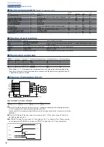
Rotation monitor output
Power down input
Note 2) CCW pulse input
Note 2) CW pulse input
DC24 G
DC24 V
M
Note 1)
Note 3)
External wiring diagram
Rotational operation
10%
50%
90%
4.0~5.5V
0~0.5V
10 s MIN.
1 s MAX.
1 s MAX.
■
Input signal specifications
■
Timing of the command pulse
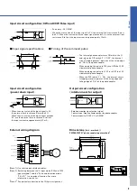
• The internal photo coupler turns ON within the
■
and, when the DIP switch
“
C
”
=
“
OFF
”
, the internal
circuit
(
stepping motor
)
operates at the rising edge
of
“
ON
”
of the photo coupler.
• When applying the pulse to CW, turn OFF the CCW
side internal photo coupler.
• When applying the pulse to CCW, turn OFF the CW
side internal photo coupler.
• When the DIP switch
“
C
”
=
“
ON
”
, the internal circuit
(
stepping motor
)
operates at the rising edge and
falling edge of
“
ON
”
of the photo coupler.
Input circuit configuration
(
CW and CCW Pulse input
)
• Pulse duty : 50 % MAX.
• When the crest value of the input signal is 5 V, the external limit resistance R must
be 0
Ω
. When the crest value of the input signal exceeds 5 V, use the external limit
resistance R to limit the input current to approximately 15 mA.
330
PM driver
photo coupler
Approx. 15 mA
+
5 V
Input signal
R
5
6
Input circuit configuration
(
power down input
)
• When the crest value of the input signal is 5 V,
the external limit resistance R must be 0
Ω
.
When the crest value of the input signal exceeds
5 V, use the external limit resistance R to limit
the input current to approximately 15 mA.
Output circuit configuration
(
rotation moni for output
)
MAX. 5 mA
MAX. 30 V
PM driver
photo coupler
Output signal
7
8
• Rotation monitor signal output signal
Contact type : Open collector output by photo coupler
Contact capacity : DC30 V, 5 mA MAX.
Dimensions
[Unit : mm
(
inch
)
]
PMDSA1S3P01
(
photo coupler input method
)
(
Note 1
)
Use twisted pair shielded cables.
(
Note 2
)
Switching between the
“
2-input mode
(
CW and CCW
input method
)”
and the
“
Pulse and direction mode
(
CK, U/D
)”
is an optional function. For more
information, contact us.
(
Note 3
)
Pay particular attention to the CN2 pin assignment.


