_
1.
INTRODUCTION
_
6
1
1
.
.
2
2
O
O
p
p
e
e
r
r
a
a
t
t
i
i
n
n
g
g
P
P
r
r
e
e
c
c
a
a
u
u
t
t
i
i
o
o
n
n
s
s
1
1
.
.
2
2
.
.
1
1
U
U
P
P
S
S
I
I
n
n
p
p
u
u
t
t
P
P
o
o
w
w
e
e
r
r
S
S
u
u
p
p
p
p
l
l
y
y
The following table shows the rated AC input power of this UPS. Use the UPS with the output voltage
*1
set in accordance with the
AC input power of the region of UPS use.
Model name
AC input voltage
AC input frequency
Input capacity
Recommended breaker capacity
of input distributor board
*4
E11B102A001 100 V, 110 V, 115 V, 120 V
*1
(55 to 150 V)
50 Hz or 60 Hz
(40 to 120 Hz
*2
)
1.1 kVA
15 A
E11B102A002 200 V, 220 V, 230 V, 240, 208 V
*1
(110 to 300 V)
10 A
*1. Set the UPS output voltage in accordance with the AC input voltage rating value. Refer to the Setting Menu Manual for details on setting changes.
*2. The range in which the UPS output frequency is synchronized with the AC input frequency differs as follows by the setting of the “UPS Operation Mode”
in the setting menu.
Note that the UPS switches to battery operation when the AC input frequency is other than the 40 to 120 Hz range.
When the UPS operation mode is set to “Fixed to double conversion”: 1%
When the UPS operation mode is set to “Auto”: 1, 3, 5%*3
*3. The setting of the frequency synchronization range can be changed. Refer to the Setting Menu Manual for details on setting changes.
The default setting is set to 3%.
*4.
Protect branch circuits by using the breaker
(UL489 compliant breaker)
of the specified capacity on distribution panels. To meet the
requirements of UL standards, always protect both polarities.
1
1
.
.
2
2
.
.
2
2
I
I
n
n
s
s
t
t
a
a
l
l
l
l
a
a
t
t
i
i
o
o
n
n
P
P
r
r
e
e
c
c
a
a
u
u
t
t
i
i
o
o
n
n
s
s
(1) Carefully consider the sensitivity current when installing a leakage circuit breaker on the input side. The maximum leakage
current of this UPS is 3 mA.
(2) Keep the necessary distance from devices that are sensitive to magnetic flux such as CRT displays as the UPS emits a slight
amount of magnetic flux.
(3) The UPS employs a fan for forced-air cooling. If you mount the UPS on a rack, verify that the rack is well ventilated. Also, verify
that the clearances specified in “3.2 Checking the Installation Space” are provided.
(4) Support rails (option) are required to mount the UPS on a rack. For details, contact your rack manufacturer or sales
representative.
(5) When the AC input power supply is single-wire grounded, always connect the ground phase to the N terminal (phase) of the
UPS outlet. For details, see “4.1 Preparation”.
(6) Do not ground the output (load) side. If the load equipment input needs to be single-wire grounded, always connect the ground
phase to the W terminal (V phase) side to prevent a power supply short-circuit caused by grounding. For details, see “4.1
Preparation”.
(7) If condensation occurs during transportation, storage, or the like due to a difference in temperature, causing moisture to adhere
to the device, leave the device alone and wait several hours for the device to dry. Failure to do so results in UPS failure. Do not
handle the UPS when condensation has occurred.
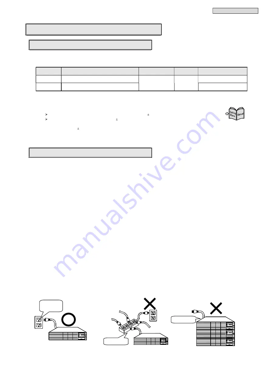
(8) Prepare a UPS dedicated outlet so as to not overload the electrical circuit.
(9) If installing multiple UPS units, do not stack the units.
Do not use
multiple wirings
Do not stack
UPS dedicated
Outlet


