


85464849248002
REFERENCE NO.
SM
831148-2
FILE NO.
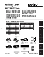
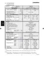
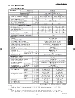
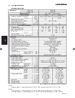
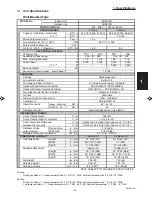
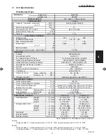
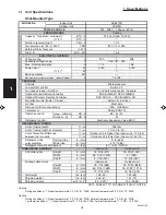
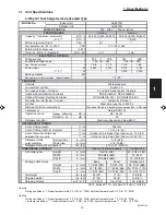
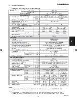
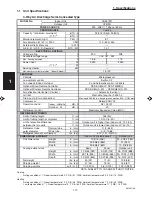
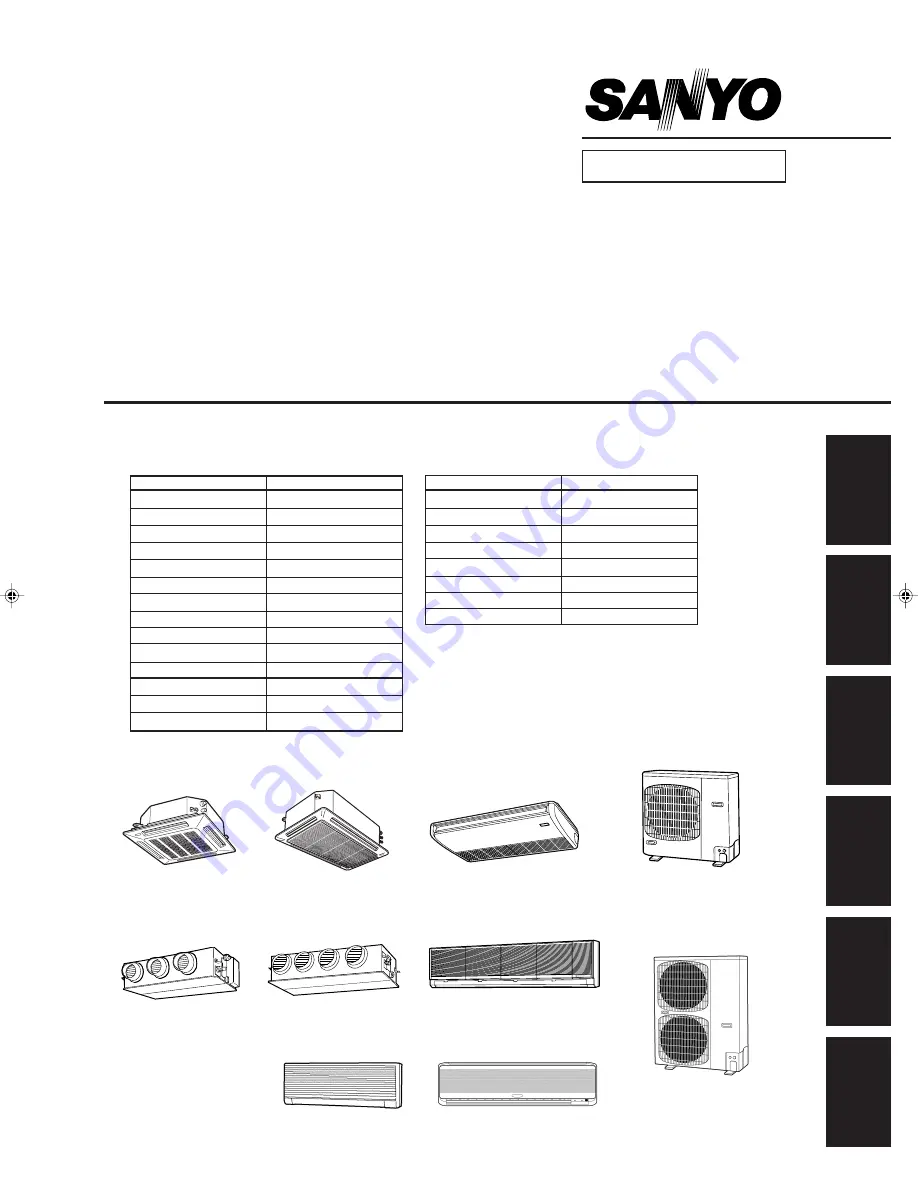
TECHNICAL DATA
&
SERVICE MANUAL
1
2
3
4
5
6
Section
XH2672R / CH2672R, C2672R
XH3672R / CH3672R, C3672R
XH4272R / CH4272R, C4272R
TH2672R / CH2672R, C2672R
TH3672R / CH3672R, C3672R
THH2672R / CH2672R
THH3672R / CH3672R
TH4272R / CH4272R, C4272R
KH2672R / CH2672R, C2672R
KH3072R / CH3072R, C3072R
KH3672R / CH3672R, C3672R
KHH2672R / CH2672R
UH2672R / CH2672R, C2672R
UH3672R / CH3672R, C3672R
SPLIT SYSTEM AIR CONDITIONER
XH2672R
XH3672R
XH4272R
CH4272R, C4272R
UH2672R
TH2672R, THH2672R
TH3672R, THH3672R
TH4272R
CH2672R, C2672R
CH3072R, C3072R
CH3672R, C3672R
KH3072R
KH3672R
Indoor Unit
Outdoor Unit
UH3672R
KHH2672R
KH2672R
OUTDOOR MODEL No.
PRODUCT CODE No.
CH2672R
854 028 20
CH3072R
854 028 21
CH3672R
854 028 22
CH4272R
854 031 87
C2672R
854 028 24
C3072R
854 028 25
C3672R
854 028 26
C4272R
854 031 88
INDOOR MODEL No.
PRODUCT CODE No.
XH2672R
854 028 32
XH3672R
854 028 33
XH4272R
854 031 89
TH2672R
854 028 35
TH3672R
854 028 36
TH4272R
854 031 90
THH2672R
854 028 38
THH3672R
854 028 39
KH2672R
854 028 28
KH3072R
854 028 29
KH3672R
854 028 30
KHH2672R
854 028 31
UH2672R
854 028 40
UH3672R
854 028 41
Summary of Contents for 000 BTU Ductless Single Zone Mini-Split Wall-Mounted Heat Pump
Page 2: ......
Page 77: ...1 2 3 4 5 6 I 73 SM831148 1 Specifications 1 4 Dimensional Data B Outdoor Unit CH4272R C4272R ...
Page 118: ......
Page 128: ...1 2 3 4 5 6 III 10 SM831148 3 Electrical data Wall Mounted Type KH2672R ...
Page 129: ...III 11 SM831148 3 Electrical data 1 2 3 4 5 6 Wall Mounted Type KH2672R Schematic Diagram ...
Page 133: ...III 15 SM831148 3 Electrical data 1 2 3 4 5 6 Wall Mounted Type KHH2672R Schematic Diagram ...
Page 135: ...III 17 SM831148 3 Electrical data 1 2 3 4 5 6 3 2 Outdoor Units CH2672R Schematic Diagram ...
Page 137: ...III 19 SM831148 3 Electrical data 1 2 3 4 5 6 3 2 Outdoor Units C2672R Schematic Diagram ...
Page 143: ...III 25 SM831148 3 Electrical data 1 2 3 4 5 6 3 2 Outdoor Units CH4272R Schematic Diagram ...
Page 145: ...III 27 SM831148 3 Electrical data 1 2 3 4 5 6 3 2 Outdoor Units C4272R Schematic Diagram ...
Page 146: ......


