


VI-3
SM831148
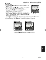
1
2
3
4
5
6
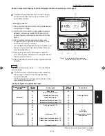
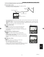
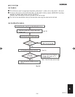
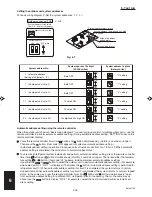
6. Test run
X, T, U, K Type
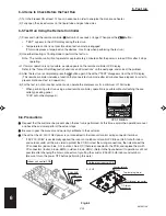
6-2. Caution
This unit may be used in a single-type refrigerant system where 1 outdoor unit is connected to 1 indoor unit.
The indoor and outdoor unit control PCBs utilize a semiconductor memory element (EEPROM). The settings
required for operation were made at the time of shipment.
Only the correct combination of indoor and outdoor units can be used.
This test run manual describes primarily the procedure when using the wired remote controller.
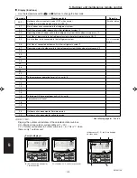
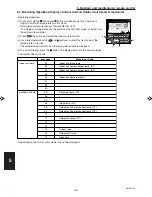
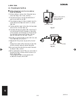
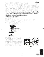
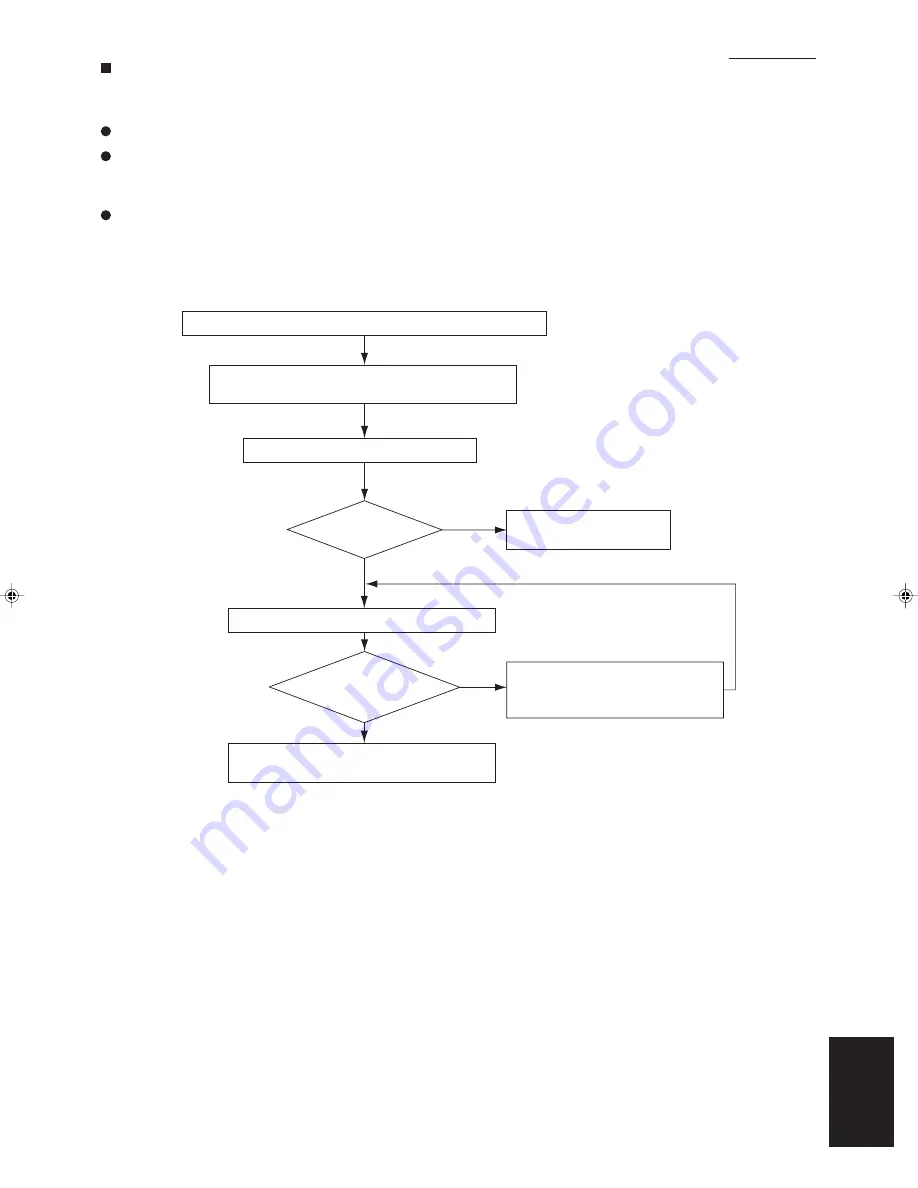
6-3. Test Run Procedure
Recheck the items (see IV-4) to check before the test run.
Turn ON the indoor and outdoor power.
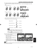
Set the remote controller to “test run.”
Return the remote controller to normal
control.
YES
NO
Automatic
address?
(See I-98)
(See VI-4)
Check the combination (wiring) of indoor and
outdoor units.
Refer to “Table of Self-Diagnostic
Functions and Corrections” to
check the system.
YES
NO
Note: Check the indoor-side drainage.
Has the
test run been
completed?
Check the warning code.
Fig. 6-3
Summary of Contents for 000 BTU Ductless Single Zone Mini-Split Wall-Mounted Heat Pump
Page 2: ......
Page 77: ...1 2 3 4 5 6 I 73 SM831148 1 Specifications 1 4 Dimensional Data B Outdoor Unit CH4272R C4272R ...
Page 118: ......
Page 128: ...1 2 3 4 5 6 III 10 SM831148 3 Electrical data Wall Mounted Type KH2672R ...
Page 129: ...III 11 SM831148 3 Electrical data 1 2 3 4 5 6 Wall Mounted Type KH2672R Schematic Diagram ...
Page 133: ...III 15 SM831148 3 Electrical data 1 2 3 4 5 6 Wall Mounted Type KHH2672R Schematic Diagram ...
Page 135: ...III 17 SM831148 3 Electrical data 1 2 3 4 5 6 3 2 Outdoor Units CH2672R Schematic Diagram ...
Page 137: ...III 19 SM831148 3 Electrical data 1 2 3 4 5 6 3 2 Outdoor Units C2672R Schematic Diagram ...
Page 143: ...III 25 SM831148 3 Electrical data 1 2 3 4 5 6 3 2 Outdoor Units CH4272R Schematic Diagram ...
Page 145: ...III 27 SM831148 3 Electrical data 1 2 3 4 5 6 3 2 Outdoor Units C4272R Schematic Diagram ...
Page 146: ......


