


VI-7
SM831148
1
2
3
4
5
6
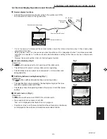
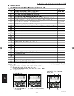
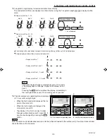
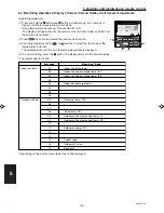
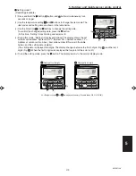
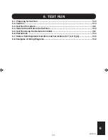
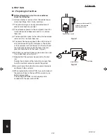
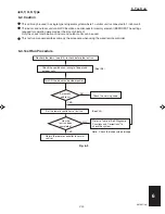
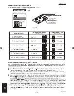
6. Test run
1 2
1
2
L2
U1
RC
U2
L1
U2
U1
G
1
2
1
2
L2
U1
RC
U2
L1
U2
U1
G
1
2
System address rotary switch
(Set to
“
0
”
at the time of shipment.)
Outdoor unit
Indoor
unit
Wired remote
controller
WHT
BLK
(Optional)
Remote controller wiring
(Field supply)
System address rotary switch
(Set to
“
0
”
at the time of shipment.)
Outdoor unit
Indoor
unit
Remote controller crossover wiring
for group control
Ground
Power supply
Single-phase
230 / 208 V
Inter-unit power line
230 / 208 V, 60 Hz
Ground
Power supply
Single-phase
230 / 208 V
Inter-unit power line
230 / 208 V, 60 Hz
1
2
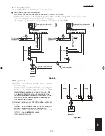
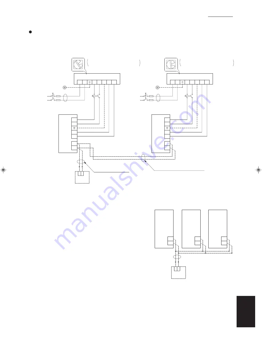
Basic wiring diagram 2
Group control (when a central control device is not used)
Simultaneous-operation multi system
A maximum of 8 indoor units can be connected to 1 remote controller.
Set the system address (refrigerant tubing system address) before turning on the remote power switch.
(Refer to “Setting the system addresses” on next page.)
(Set using the system address rotary switch on the outdoor unit control PCB.)
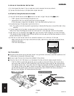
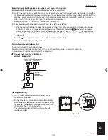
(Wiring procedure)
(1) Connect the remote controller to the indoor unit remote
controller wiring.
Use the remote controller connection wire coming from
the indoor unit, and field-supply wire and a wire joint to
complete the connection as shown in Fig. 6-6b. The
remote controller connection wire coming from the
indoor unit includes a connector, therefore cut off the
connector and use the wire joint to connect the wire
from the remote controller.
(2) Connect the indoor units (U1, U2) and the outdoor units
(1, 2).
Connect the other outdoor units and indoor units (with
different refrigerant systems) in the same way.
Connect the inter-unit control wiring to the indoor units
(U1, U2) for each refrigerant system.
(Inter-unit control wiring)
Fig. 6-6b
1 2
RC
RC
RC
Indoor
unit 1
Indoor
unit 2
Indoor
unit 3
Wired remote
controller
WHT
BLK
(Optional)
Fig. 6-6a
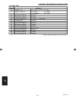
Summary of Contents for 000 BTU Ductless Single Zone Mini-Split Wall-Mounted Heat Pump
Page 2: ......
Page 77: ...1 2 3 4 5 6 I 73 SM831148 1 Specifications 1 4 Dimensional Data B Outdoor Unit CH4272R C4272R ...
Page 118: ......
Page 128: ...1 2 3 4 5 6 III 10 SM831148 3 Electrical data Wall Mounted Type KH2672R ...
Page 129: ...III 11 SM831148 3 Electrical data 1 2 3 4 5 6 Wall Mounted Type KH2672R Schematic Diagram ...
Page 133: ...III 15 SM831148 3 Electrical data 1 2 3 4 5 6 Wall Mounted Type KHH2672R Schematic Diagram ...
Page 135: ...III 17 SM831148 3 Electrical data 1 2 3 4 5 6 3 2 Outdoor Units CH2672R Schematic Diagram ...
Page 137: ...III 19 SM831148 3 Electrical data 1 2 3 4 5 6 3 2 Outdoor Units C2672R Schematic Diagram ...
Page 143: ...III 25 SM831148 3 Electrical data 1 2 3 4 5 6 3 2 Outdoor Units CH4272R Schematic Diagram ...
Page 145: ...III 27 SM831148 3 Electrical data 1 2 3 4 5 6 3 2 Outdoor Units C4272R Schematic Diagram ...
Page 146: ......


