


1
2
3
4
5
6
I-86
SM831148
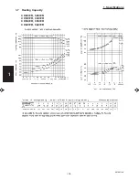
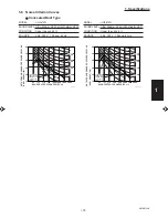
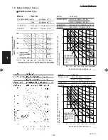
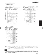
1. Specifications
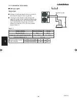
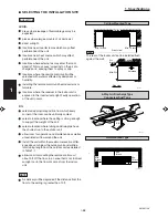
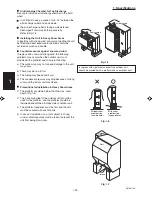
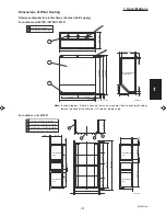
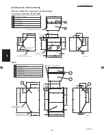
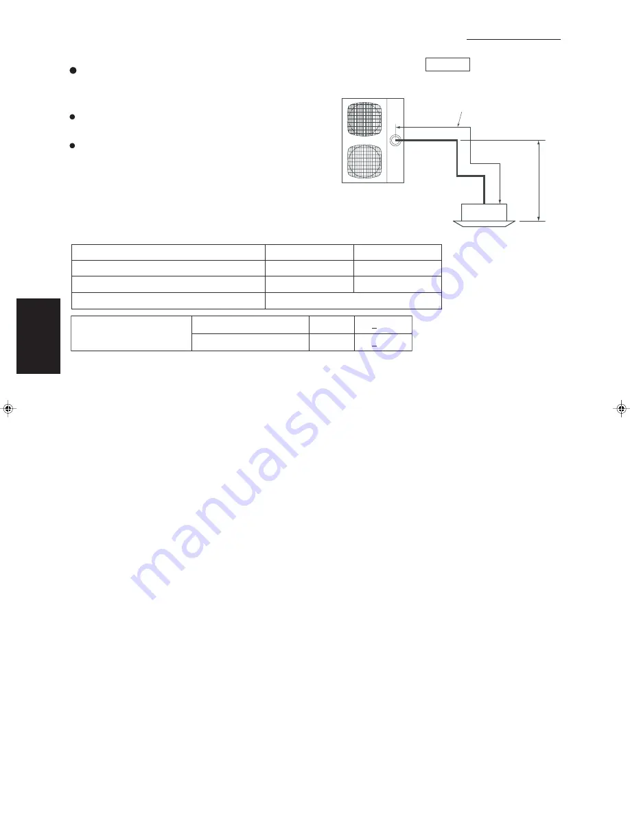
1-11 Installation Instructions
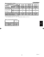
Tubing Length
Single type
Refrigerant tubing between the indoor and outdoor
units should be kept as short as possible.
The length of the refrigerant tubes between the
indoor and outdoor units are limited by the elevation
difference between the 2 units. During tubing work,
try to make both the tubing length (L) and the
difference in elevation (H1) as short as possible.
Refer to Table 1-2.
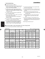
Table 1-1
Single
H1
Maximum length
H1
H1
< 100
< 50
Maximum indoor-outdoor
height difference
If outdoor unit is higher
If outdoor unit is lower
Indoor unit type
26, 30, 36 types
42 type
Maximum length
165 ft.
165 ft.
Charge-less tubing length (actual length)
10 – 100 ft.
15 – 100 ft.
Additional charge per 1 ft.
0.43 oz.
Summary of Contents for 000 BTU Ductless Single Zone Mini-Split Wall-Mounted Heat Pump
Page 2: ......
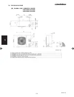
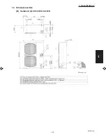
Page 77: ...1 2 3 4 5 6 I 73 SM831148 1 Specifications 1 4 Dimensional Data B Outdoor Unit CH4272R C4272R ...
Page 118: ......
Page 128: ...1 2 3 4 5 6 III 10 SM831148 3 Electrical data Wall Mounted Type KH2672R ...
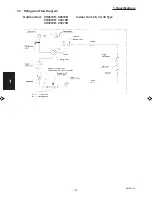
Page 129: ...III 11 SM831148 3 Electrical data 1 2 3 4 5 6 Wall Mounted Type KH2672R Schematic Diagram ...
Page 133: ...III 15 SM831148 3 Electrical data 1 2 3 4 5 6 Wall Mounted Type KHH2672R Schematic Diagram ...
Page 135: ...III 17 SM831148 3 Electrical data 1 2 3 4 5 6 3 2 Outdoor Units CH2672R Schematic Diagram ...
Page 137: ...III 19 SM831148 3 Electrical data 1 2 3 4 5 6 3 2 Outdoor Units C2672R Schematic Diagram ...
Page 143: ...III 25 SM831148 3 Electrical data 1 2 3 4 5 6 3 2 Outdoor Units CH4272R Schematic Diagram ...
Page 145: ...III 27 SM831148 3 Electrical data 1 2 3 4 5 6 3 2 Outdoor Units C4272R Schematic Diagram ...
Page 146: ......


