-22-
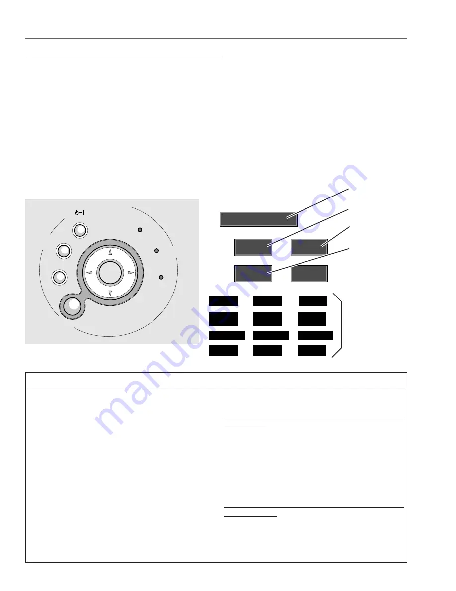
To enter the service mode
To enter the “Service Mode”, press and hold the
MENU
and
INPUT buttons
on the projector at the same time for
more than 3 seconds. The service menu appears on the screen as follows.
To adjust service data
Select the adjustment item no. by pressing the pointer
UP
or
DOWN button
, and change the data value by press-
ing the
VOLUME –
or
button
. Refer to the “Service Adjustment Data Table” for further description of
adjustment item no. and data value.
To exit the service mode
To exit the service mode, press the
POWER ON-OFF button
on the projector or remote control unit.
●
Service Adjustment Menu Operation
IC1841 on the main board stores the data for the serv-
ice adjustments, and should not be replaced except for
the case of defective device.
If replaced, the re-adjustments are required following to
the “Electrical Adjustments”.
The data of lamp replacement counter is stored in the
IC1841.
Please note that the lamp replace counter will be reset
when the memory IC (IC1841) is replaced.
(Lamp replace counter cannot be set to the previous
value.)
●
Caution to memory IC replacement
When IC1841 is replaced with new one, the CPU
writes down the default data of the service adjustments
to the replaced IC as the mentioned on the service
adjustment table. As these data are not the same data
as factory shipped data, it should be required to per-
form the re-adjustments following to the “Electrical
Adjustments”.
Please note that in this case the lamp replace counter
will be reset.
●
Caution of Main Board replacement (in the case
IC1841 is not defective)
When the main board is replaced, IC1841 should be
replaced with the one on previous main board. After
replacement, it should be required to perform the re-
adjustments following to the “Electrical Adjustments”.
In this case, the lamp replace counter can be kept the
value as before.
●
Memory IC Replacement
ON
-
OFF
POWER
AUTO SET UP
INPUT
WARNING
LAMP
REPLACE
MENU
V
O
L
U
M
E
–
V
O
L
U
M
E
+
SELECT
■
Electrical Adjustments
Computer
70
100
35
Service Mode
TempA
TempB
TempC
Fan1Speed
Fan2Speed
Fan3Speed
32.10
43.21
45.67
97
105
79
Data value
Item No.
Input Mode
Version No.
Note :
This part of display
is available at the
service mode
No.80 - 123.
Summary of Contents for 1 122 280 00
Page 50: ... 50 IC Block Diagrams BA7078AF Sync Detector IC5301 AN5870SB RGB SW G_Sync Separator IC5201 ...
Page 51: ... 51 IC Block Diagrams BA9743AFV DC DC Converter IC371 FA5502 P F Control IC621 ...
Page 52: ... 52 IC Block Diagrams LM4889M Audio Amplifier IC5031 PW168A Scaler Main CPU IC301 ...
Page 53: ... 53 IC Block Diagrams NJW1141 Audio Selector IC5001 STR Z2156 Power Switching Control IC631 ...
Page 78: ...MM5 XU4700 78 L2 Prism LCD panel Ass y Mechanical Parts List L2 c L2 a L2 b L2 e L2 d L2 ...
Page 79: ...MM5 XU4700 79 Mechanical Parts List A D D E B C C L19 L13 L5 L8 L18 L11 L1 L3 L7 L12 L6 L14 ...
Page 82: ... MM5A Oct 2004 BB 400 Printed in Japan SANYO Electric Co Ltd ...
Page 86: ...Diagrams Drawings MM5 XU47 ...


