-19-
5
9
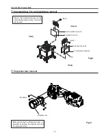
Fig.8
1
6
10
Optical Parts Disassembly
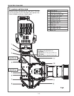
When mounting or assembling the optical parts in the opti-
cal unit, the parts must be mounted in the specified loca-
tion and direction as shown in figure below.
2
3
4
8
8
11
,
Locations and Directions
direction of Integrator lens-out
PLc-XW55A
Rugged surface is facing to the PBS side.
PLc-XW50A
Rugged surface is facing to the lamp side.
The printed part no.
comes to this side.
The printed part no.
comes to this side.
No. Parts Name
1
Integrator lens (OUT)
Prism beam splitter (PBS)
3
Condenser lens (OUT)
4
Dichroic mirror (B)
5
Dichroic mirror (G)
6
Condenser lens (G)
7
Relay Lens (IN)
8
Mirror (R)
9
Condenser lens (R)
10
Condenser lens (B)
11
Mirror (B)
7
Summary of Contents for 1 122 356 20
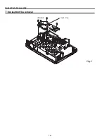
Page 18: ... 18 Optical Parts Disassembly m Optical Unit Top removal M3x8 x5 Optical top Fig 7 ...
Page 53: ... 53 IC Block Diagrams FA5502 P F Control IC621 L3E6100D D A S H LCD Driver IC501 IC531 IC561 ...
Page 54: ... 54 IC Block Diagrams L3E07072 LCD Driver Gamma Correction IC401 M62393 DAC IC3531 ...
Page 55: ... 55 IC Block Diagrams NJW1141 Audio Control IC5001 ...
Page 81: ...KR6 XW55A00 KP6 XW50A00 81 Mechanical Parts List ...
Page 82: ... KR6AD Jun 2007 DC 350 Printed in Japan SANYO Electric Co Ltd ...


