-3-
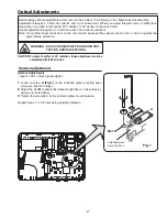
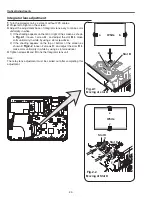
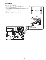
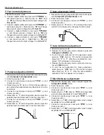
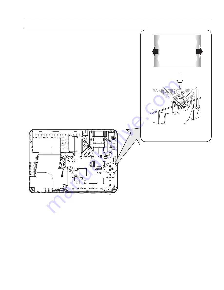
Fig.3
A
Slot B
a
b
b
Moving of slot B
a
White
1
Turn the projector on by a state of without FPC cables.
2
Project all of lights on the screen.
3
Adjust the adjustment base of relay lens assy to make color unifor-
mity in white.
If the shading appears on the left or right of the screen as shown in
Fig.3
, loosen 1 screw
A
, and adjust the slot B to make color unifor-
mity in white by using a slot screwdriver.
4
Tighten the screws
A
to fix the relay lens unit.
Relay lens-Out adjustment
Optical Adjustments
Summary of Contents for 1 122 356 20
Page 18: ... 18 Optical Parts Disassembly m Optical Unit Top removal M3x8 x5 Optical top Fig 7 ...
Page 53: ... 53 IC Block Diagrams FA5502 P F Control IC621 L3E6100D D A S H LCD Driver IC501 IC531 IC561 ...
Page 54: ... 54 IC Block Diagrams L3E07072 LCD Driver Gamma Correction IC401 M62393 DAC IC3531 ...
Page 55: ... 55 IC Block Diagrams NJW1141 Audio Control IC5001 ...
Page 81: ...KR6 XW55A00 KP6 XW50A00 81 Mechanical Parts List ...
Page 82: ... KR6AD Jun 2007 DC 350 Printed in Japan SANYO Electric Co Ltd ...


