-5-
Cleaning
cleaning with air spray
1. Remove the cabinet top following to “Mechanical Dis-
assemblies”.
. Clean up the LCD panel and polarizing plate by using
the air spray from the cabinet top opening.
caution:
Use a commercial (inert gas) air spray designed for
cleaning camera and computer equipment. Use a resin-
based nozzle only. Be vary careful not to damage optical
parts with the nozzle tip. Never use any kind of cleanser
on the unit. Also, never use abrasive materials on the
unit as this may cause irreparable damage.
After long periods of use, dust and other particles will accumulate on the LCD panel, prism, mirror, polarized glass,
lens, etc., causing the picture to darken or color to blur. If this occurs, clean the inside of optical unit.
Remove dust and other particles using air spray. If dirt cannot be removed by air spray, disassemble and clean the
optical unit.
disassembly cleaning
Disassembly cleaning method should only be performed
when the unit is considerable dirty and cannot be suf-
ficiently cleaned by air spraying alone.
Be sure to readjust the optical system after perform-
ing disassembly cleaning.
1. Remove the cabinet top and main units following to
“Mechanical Disassemblies”.
. Remove the optical base top following to “Optical Unit
Disassemblies”. If the LCD panel needs cleaning, re-
move the LCD panel unit following to “LCD panel re-
placement”.
3. Clean the optical parts with a soft cloth. Clean ex-
tremely dirty areas using a cloth moistened with al-
cohol.
caution:
The surface of the optical components consists of mul-
tiple dielectric layers with varying degrees of refraction.
Never use organic solvents (thinner, etc.) or any kind of
cleanser on these components.
Since the LCD panel is equipped with an electronic cir-
cuit, never use any liquids (water, etc.) to clean the unit.
Use of liquid may cause the unit to malfunction.
Summary of Contents for 1 122 356 20
Page 18: ... 18 Optical Parts Disassembly m Optical Unit Top removal M3x8 x5 Optical top Fig 7 ...
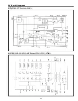
Page 53: ... 53 IC Block Diagrams FA5502 P F Control IC621 L3E6100D D A S H LCD Driver IC501 IC531 IC561 ...
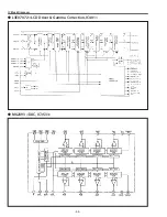
Page 54: ... 54 IC Block Diagrams L3E07072 LCD Driver Gamma Correction IC401 M62393 DAC IC3531 ...
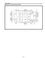
Page 55: ... 55 IC Block Diagrams NJW1141 Audio Control IC5001 ...
Page 81: ...KR6 XW55A00 KP6 XW50A00 81 Mechanical Parts List ...
Page 82: ... KR6AD Jun 2007 DC 350 Printed in Japan SANYO Electric Co Ltd ...

