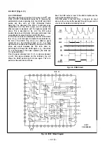
[Feedback-type soft limiter]
The band which is b oosted can be limited by the positive
feedback-type soft limiter, with the result that signal inver
sion can be prevented. The basic configuration is shown in
Fig. 4-2.
The circuit comprises a positive feedback loop which
consists of a limiter, LPF and HPF. The limiter can be
thought of as a circuit which varies the gain in accordance
with the input level, so that when the input level is sufficiently
HPF
Limiter
LPF
high, the circuit characteristics become almost flat. With any
drop in the input level, peaking characteristics occur
centring around a frequency which is deter 1nined by the
product of the time constants of the LPF ana
r1 PF.
Accordingly, these peaking characteristics
a r e
used to make
it possib le to compensate for drops in the high output range,
so that signal inversion can be prevented.
Limiter
Demodulator
Fig.
4-2.
4-8. CHROMA SIGNAL RECORDING SYSTEM
4-8-1 .
EE System
After the CAM C signal is switched at IC1 52, it is input to
Pin @ of IC1 01 , where it is mixed with the luminance signal
and output from Pin @ . When a cable is connected to the S
terminal, the signal is output from S C OUT.
4-8-2.
Recording System
The route of the recording chroma signal can be broadly
classified into the following two types.
(1 ) Route passing through the Y/C separation circuit
(2) Route passing around the Y/C separation circuit
The 2H delay signal which uses Y/C separation is created
by the CCD delay line of IC1 1 1 .
For a composite VI DEO signal, the route is (1 ); for CAM C
and S C, the route is (2). (For PAL, however, route (2) only
is used.) In either case, the signal is ultimately output from
Pin @ of IC 1 21 to the ACC circuit, where the burst
amplitude is made constant, after which chroma emphasis
and burst emphasis are applied. The recording converter
then converts the signal to a low band frequency, and the
signal is output from Pin @ .
At this time, the phase is rotated 90
°
for each field (PS),
and during playback, crosstalk from neighbouring tracks is
removed by the comb filter.
The low band conversion carrier chroma signal passes
through the LPF, AFM and TRAP circuits, after which the
AFM signal and the ATF pilot signal are added. The signal
is then input to Pin ® of the recording and playback
amplifier IC1 91 and recorded onto the tape together with
the FM luminance signal.
Furthermore, the FM luminance signal is used as the b ias
current in this case.
4-9. CHROMA SIGNAL PLAYBACK SYSTEM
The chroma signal which is played back by IC1 91 passes
through the ATF trap and 1 .3 MHz LPF to remove the
unnecessary components, after which it is input to Pin @ of
IC1 21 . After the burst amplitude is made constant at the
ACC circuit, the signal is converted to a 4.43 M Hz carrier
wave and sent to IC1 01 . The comb filter at IC1 01 removes
the crosstalk component, after which the signal passes
through the BPF and is input to Pin @ of IC1 21 . For H i8
mode, because the luminance signal band is as wide as 5
M Hz, delay lines which are comprised of comb filters are
provided for the luminance signal (1 H) and the chroma
signal (1 H) (2H for PAL). IC1 1 5 is the delay line for the
luminance signal, and IC1 1 1 is the one for the chroma
signal.
The waveform of the chroma signal which is input from
Pin @ is restored to its original form by the burst de
emphasis and chroma de-emphasis circuits, in the reverse
to the procedure during recording, after which it is output
from Pin @ of IC1 21 .
After this, the signal is output via the PAL JOG circuit which
compensates the chroma array in special playback mode.
- 4-27 -


