

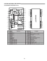
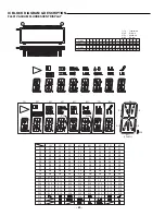
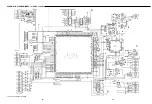
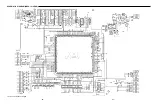
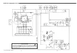
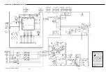


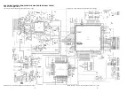

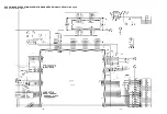
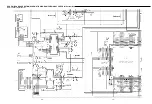
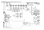

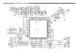

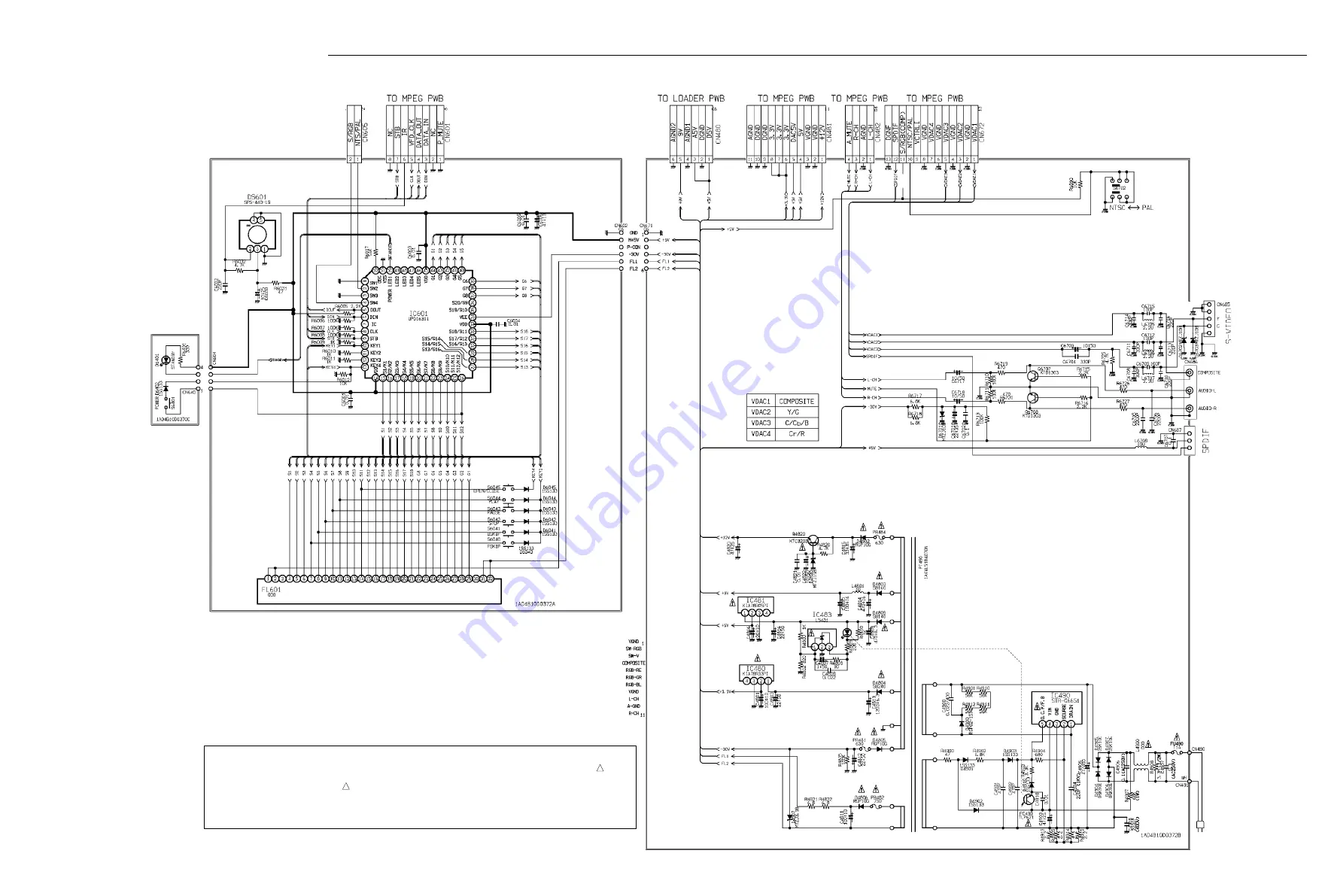
SCHEMATIC DIAGRAM(MAIN for AU,SS)
This is a basic schematic diagram.
- 72 -
- 73 -
PRODUCT SAFETY NOTICE
Each precaution in this manual should be followed during servicing. Components identified with the IEC symbol
!!!
in the
parts list and the schematic diagram designated components in which safety can be of special significance. When
replacing a component identified by
!!!
, use only the replacement parts designated, or parts with the same ratings of
resistance, wattage or voltage that are designated in the parts list in this manual. Leakage-current or resistance
measurements must be made to determine that exposed parts are acceptably insulated from the supply circuit before
returning the product to the customer.
Summary of Contents for 137 103 01
Page 47: ...SCHEMATIC DIAGRAM MPEG for AU SS and CA This is a basic schematic diagram 64 65 ...
Page 48: ...SCHEMATIC DIAGRAM MPEG for XE UK This is a basic schematic diagram 66 67 ...
Page 53: ...SANYO Technosound Co Ltd Osaka Japan Apr 01 3500 BB Printed in Japan ...
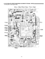
Page 61: ...MPEG P W BOARD SCHEMATIC DIAGRAM FOR WAVEFORM CHECK This is a basic waveform check 32 33 ...
Page 62: ...AMP P W BOARD SCHEMATIC DIAGRAM FOR WAVEFORM CHECK This is a basic waveform check 34 35 ...
Page 63: ...WIRING DIAGRAM MPEG A SIDE 68 69 ...
Page 64: ...WIRING DIAGRAM MPEG B SIDE 70 71 ...
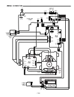
Page 65: ...WIRING DIAGRAM DG SOCKET POWER SW for AU SS 74 75 DG SOCKET POWER SW ...
Page 66: ...WIRING DIAGRAM FRONT for AU SS 76 77 ...
Page 67: ...WIRING DIAGRAM DG SOCKET POWER SW for XE UK 80 81 DG SOCKET POWER SW SCART SW ...
Page 68: ...WIRING DIAGRAM FRONT for XE UK 82 83 ...
Page 69: ...WIRING DIAGRAM DG SOCKET POWER SW for CA 86 87 DG SOCKET POWER SW ...
Page 70: ...WIRING DIAGRAM FRONT for CA 88 89 ...
Page 72: ...SCHEMATIC DIAGRAM DVD TOP LEFT This is a basic schematic diagram 92 93 ...
Page 73: ...SCHEMATIC DIAGRAM DVD BOTTOM LEFT This is a basic schematic diagram 94 95 ...
Page 74: ...SCHEMATIC DIAGRAM DVD TOP RIGHT This is a basic schematic diagram 96 97 ...
Page 75: ...SCHEMATIC DIAGRAM DVD BOTTOM RIGHT This is a basic schematic diagram 98 99 ...


