

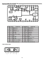
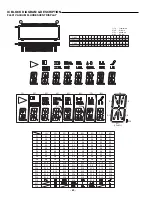
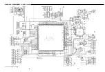
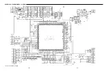
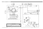
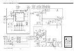


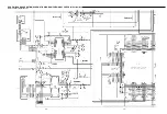
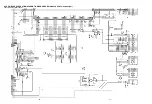

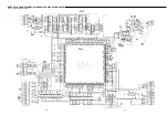

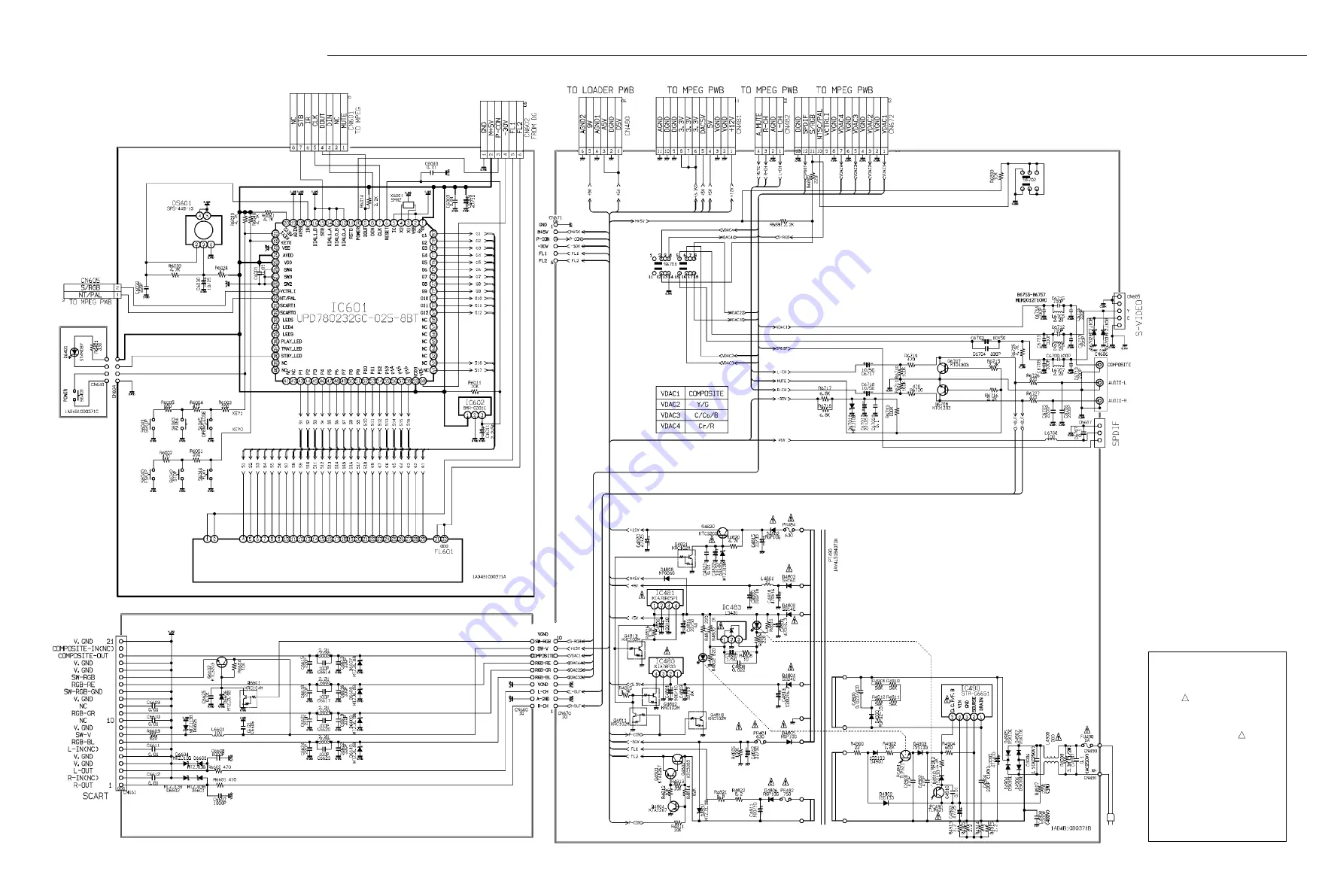
SCHEMATIC DIAGRAM(MAIN for XE,UK)
PRODUCT SAFETY NOTICE
Each precaution in this manual should
b e f o l l o w e d d u r i n g s e r v i c i n g .
Components identified with the IEC
symbol
!!!
in the parts list and the
s c h e m a t i c d i a g r a m d e s i g n a t e d
components in which safety can be of
special significance. When replacing a
component identified by
!!!
, use only
the replacement parts designated, or
p a r t s w i t h t h e s a m e r a t i n g s o f
resistance, wattage or voltage that are
designated in the parts list in this
manual. Leakage-current or resistance
measurements must be made to
determine that exposed parts are
acceptably insulated from the supply
circuit before returning the product to
the customer.
- 78 -
- 79 -
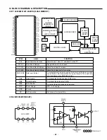
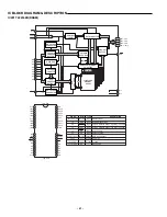
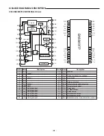
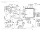
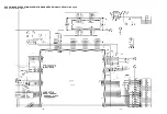
This is a basic schematic diagram.
Summary of Contents for 137 103 01
Page 47: ...SCHEMATIC DIAGRAM MPEG for AU SS and CA This is a basic schematic diagram 64 65 ...
Page 48: ...SCHEMATIC DIAGRAM MPEG for XE UK This is a basic schematic diagram 66 67 ...
Page 53: ...SANYO Technosound Co Ltd Osaka Japan Apr 01 3500 BB Printed in Japan ...
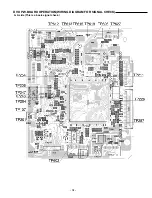
Page 61: ...MPEG P W BOARD SCHEMATIC DIAGRAM FOR WAVEFORM CHECK This is a basic waveform check 32 33 ...
Page 62: ...AMP P W BOARD SCHEMATIC DIAGRAM FOR WAVEFORM CHECK This is a basic waveform check 34 35 ...
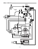
Page 63: ...WIRING DIAGRAM MPEG A SIDE 68 69 ...
Page 64: ...WIRING DIAGRAM MPEG B SIDE 70 71 ...
Page 65: ...WIRING DIAGRAM DG SOCKET POWER SW for AU SS 74 75 DG SOCKET POWER SW ...
Page 66: ...WIRING DIAGRAM FRONT for AU SS 76 77 ...
Page 67: ...WIRING DIAGRAM DG SOCKET POWER SW for XE UK 80 81 DG SOCKET POWER SW SCART SW ...
Page 68: ...WIRING DIAGRAM FRONT for XE UK 82 83 ...
Page 69: ...WIRING DIAGRAM DG SOCKET POWER SW for CA 86 87 DG SOCKET POWER SW ...
Page 70: ...WIRING DIAGRAM FRONT for CA 88 89 ...
Page 72: ...SCHEMATIC DIAGRAM DVD TOP LEFT This is a basic schematic diagram 92 93 ...
Page 73: ...SCHEMATIC DIAGRAM DVD BOTTOM LEFT This is a basic schematic diagram 94 95 ...
Page 74: ...SCHEMATIC DIAGRAM DVD TOP RIGHT This is a basic schematic diagram 96 97 ...
Page 75: ...SCHEMATIC DIAGRAM DVD BOTTOM RIGHT This is a basic schematic diagram 98 99 ...


